
Generator Synchronization Systems Explained
Connecting two live AC sources is the most unforgiving switching operation in the power room—done right it is invisible, done wrong it is an event the hardware remembers
Introduction
A single generator backing up a building is a simple story: start, run, carry the load. The story becomes more capable—and more demanding—the moment a second machine must join a live bus. Parallel operation multiplies capacity, adds redundancy, enables maintenance without shutdown and allows right-sizing the running set to the actual load. It also introduces the most technically demanding control problem in the engine room: before one breaker closes on another running machine, three alternating quantities that never sit still must be brought into agreement, deliberately and within tight windows.
That is the job of the generator synchronization system: the sensors, controllers, engine-governor and AVR interfaces and protective relays that turn a physically violent act—connecting two independent rotating machines—into a routine, sub-second event. Buyers encounter this world in fragments: a synchronizing panel line item, a “sync check relay,” a droop setting nobody remembers commissioning. This guide assembles the fragments into a working understanding: what must match before closing, how the system matches it, how machines share load afterward, and what the checks and failure modes look like in practice.
For where synchronized generator sets sit in a facility’s power architecture—including hybrid designs with storage—start from our data center power equipment range.
What Synchronization Must Achieve
Two AC sources can be connected safely only when four conditions agree. Voltage: the incoming machine’s terminal voltage must match the bus—typically within a few percent—because a voltage difference drives reactive current between machines the instant the breaker closes. Frequency: the incoming machine’s speed must match the bus frequency within a fraction of a hertz, because frequency difference is exactly a rapidly rotating phase error. Phase angle: at the moment of closing, the rotor positions must align within a narrow window—conventionally under about ten degrees—so the machines’ voltage waves peak together. Phase sequence: the rotation order of the three phases must be identical, a one-time wiring truth verified at commissioning, because a wrong sequence is not a transient but a permanent fault condition.
Why the strictness? Because closing out of window is not like closing onto a dead bus. Two sources at different phase angles see the difference as a voltage across a near-zero impedance—producing an electromechanical shock the machines and their couplings absorb as torque, sometimes violently. Within the window, the closing is gentle: a small power exchange pulls the rotors into step within a second, and two machines become one bus. The entire art of the synchronizing system is making that window arrive reliably and closing inside it, every time, without an operator’s reflexes being part of the safety case.
How a Synchronizing Panel Works
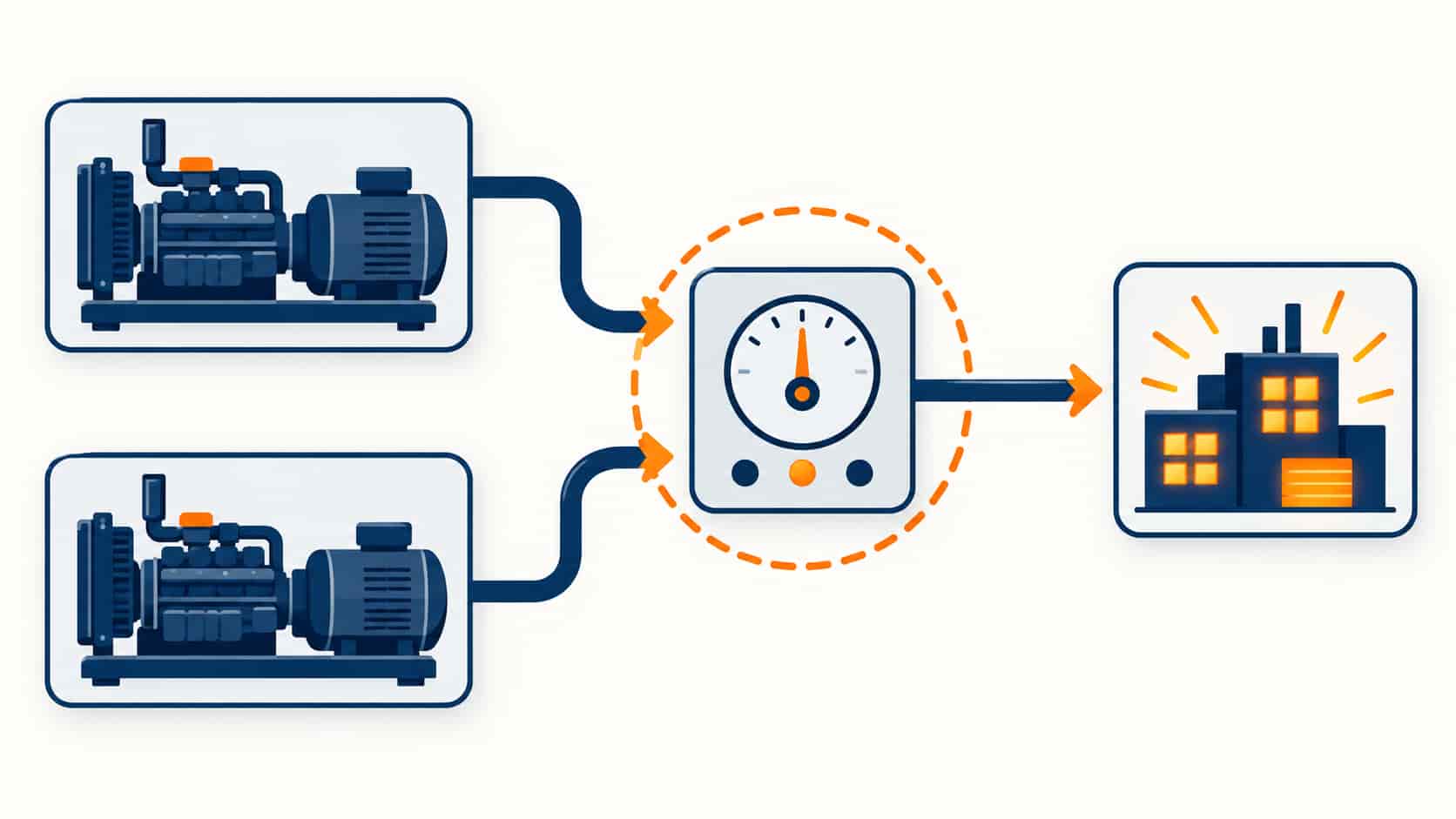
The synchronizing panel is a closed-loop controller watching both sources and steering the incoming machine onto the bus. Its voltage-matching loop commands the generator’s AVR to raise or lower excitation until terminal voltage matches the bus. Its speed-matching loop commands the engine governor to nudge frequency up or down—slightly faster than the bus so the phase angle drifts slowly through zero rather than racing past it. The sync-check relay continuously computes the three live conditions—voltage difference, frequency difference, phase angle—and permits the close command only inside the window, typically with a predicted time-to-zero-angle calculation so the breaker’s own closing time lands the contacts together at alignment.
The panel’s output is therefore not a command but a permissive: the breaker closes when physics agrees, not when an operator or a timer decides. Modern systems add the intelligence around that core: automatic sequencing of which machine starts and joins next, rotation of duty between sets, warm-up and cool-down periods, and the alarm trail for every refused close attempt. Manual operation survives as a back mode—an operator watching a synchroscope and closing on instruction—but the design intent is that reflexes are never the difference between a routine join and a bus event.
After the Breaker Closes: Load Sharing
Connected is not the finish; two machines joined on a bus must now divide the load stably. Real power (kilowatts) sharing is governed by the governors: in the traditional droop scheme, each machine’s frequency is allowed to sag a few percent from no-load to full-load, so the machines settle into proportional sharing naturally—simple, robust, but with a bus frequency that varies with load. Isochronous load sharing uses active communication between governors to hold frequency constant while dividing kilowatts exactly—tighter control, more electronics, the norm in modern critical-power plants.
Reactive power (kVAR) sharing is governed by the AVRs, and it is the subtler half. Machines whose voltage regulation curves are not coordinated will trade circulating current—current that flows between machines doing no external work while heating windings and confusing protections. The same droop-or-iso choice exists on the reactive side, coordinated AVR control is its modern answer, and commissioning must verify kVAR sharing at several load levels, not assume it. Load sharing done right is invisible: the bus frequency and voltage sit at nominal, ammeters read proportionally, and nothing hunts.
Synchronization Modes and Where They Fit
“Synchronization system” covers a ladder of automation levels, and quotations should state which rung is being supplied:
| Mode | How It Works | Best Suited For |
|---|---|---|
| Manual (synchroscope) | Operator matches meters and closes by hand under supervision | Small plants, commissioning training, backup mode of last resort |
| Semi-automatic | System matches and signals the window; operator confirms the close | Sites wanting a human decision point without manual matching |
| Automatic synchronizing | Controller matches, predicts alignment and closes; operator supervises | Standard for multi-genset standby plants in critical facilities |
| Automatic + load sharing | Full auto-sync plus governor/AVR load-sharing control across the running set | Data centers, hospitals, plants where sets start and stop by load |
| Utility paralleling | Synchronizes with the grid for transfer, peak shaving or export under agreement | Peak-shaving plants, cogeneration, utility-approved open/closed transition |
The top and bottom rungs bracket the buyer’s world. Below full automation, plants accept operator dependency and slower sequences—acceptable where load continuity is measured in minutes. Above it, utility paralleling introduces the grid operator as a party: protection settings, import/export limits and interconnection agreements become part of the specification, and the sync system must satisfy the utility’s witness tests as well as the plant’s.
The Pre-Close Checklist
Whether the panel is automatic or a human stands at the synchroscope, the physics is the same. The parameters a commissioning engineer verifies—and the tolerances a good specification names—look like this:
| Check | What Is Verified | Typical Tolerance |
|---|---|---|
| Phase sequence | A-B-C rotation identical on machine and bus | Mandatory matchâno tolerance |
| Voltage difference | Incoming terminal voltage vs bus voltage | Within roughly 5â10% |
| Frequency difference | Speed of incoming machine vs bus | Within ~0.1â0.2 Hz |
| Phase angle at close | Rotor alignment at breaker contact touch | Within ~10°, auto systems aim lower |
| Breaker timing | Closing time compensated in the close prediction | Per breaker datasheet, verified by test |
| Sharing settings | Governor droop/iso and AVR coordination across the set | Consistent scheme on every machine |
| Protection in service | Reverse power, overcurrent and sync-check relays armed | Per coordination study |
Common Failure Modes
Synchronization problems announce themselves in characteristic ways. Refused closes—the panel allows nothing—are usually not faults but the system working: a drifting bus frequency, an AVR setpoint wrong after maintenance, a breaker whose closing time changed after servicing and no longer matches the prediction. Hunting—load swinging gently between machines—points to governor dead bands or mismatched droop settings fighting each other. Circulating current between machines at light load points to uncoordinated AVRs. Each is a settings conversation, not a hardware emergency—provided someone recognizes the signature.
The genuine emergencies come from window violations and protection gaps: a manual close that beat the synchroscope by a few degrees, a sync-check relay bypassed “temporarily” during commissioning and never returned, a reverse-power relay whose trip actually saved a machine from motoring. The discipline that prevents them is procedural: sync-check supervised closes as the standing rule, settings locked and logged after commissioning, and periodic verification that the automatic system still closes inside the window it was tuned for.
When One Generator Is the Answer
Parallel capability is complexity purchased for a reason, and some projects do not have that reason. A facility whose entire critical load one machine carries comfortably, with a rental agreement covering the beyond-design case, may never justify synchronizing gear, bus-paralleling switchgear and the commissioning depth that keeps them honest. The same logic scales up: two machines sized so that either carries the full load (a 2N energy tier) can alternate rather than parallel—each starts on a dead bus, which is a simpler control problem by an order of magnitude.
The honest decision inputs are: does the load ever exceed one machine, is maintenance without downtime a requirement, and does the operating pattern reward right-sizing the running set? Where all three answers are no, spend the budget on a better single machine and a cleaner switching scheme. Where any answer is yes, parallel capability pays—but spec it as the full system: controls, breakers, protection and the commissioning that proves them together. Our overview of generator and storage hybrid systems covers the increasingly common case where the second “machine” on the bus is a battery inverter, which synchronizes by different means and adds its own coordination questions.
Specification Checklist for a Synchronizing Plant
Whether the quote covers one panel or a multi-set plant, these items make offers comparable:
- Scope split: which party supplies controllers, breakers, PTs/CTs, wiring and commissioning—named, not assumed.
- Automation level: which synchronization mode from the table, with operator actions at each step defined.
- Load sharing scheme: droop or isochronous, kW and kVAR, and the coordination plan across the machine fleet.
- Sequence logic: start order, duty rotation, warm-up/cool-down, load-dependent start/stop thresholds.
- Protection package: sync-check, reverse power, overcurrent settings and the coordination study behind them.
- Witness testing: actual paralleling tests at FAT and on site—closing under window, load pickup, sharing verification at multiple load levels.
- Integration: signals to the site’s BMS/SCADA, and compatibility with any storage inverter on the same bus.
- Documentation and training: settings record, operating procedures for manual backmode, and operator training scope.
Conclusion
A synchronization system is a small amount of hardware doing a large amount of physics: matching voltage, frequency and phase between rotating machines, closing in the window, and then making two engines behave like one disciplined source. The engineering lives in the tolerances, the coordination of governors and AVRs, and the protections that stand behind the breaker—none of it visible on the day everything works, all of it decisive on the day it does not.
Specify the automation level the operation actually needs, put the tolerances and witness tests in the contract, and keep the settings locked after commissioning. And when the plant design includes storage alongside the gensets, the team at KXY E-Power Group engineers the synchronization and control scheme across the whole hybrid bus—generators, storage and switchgear coordinated as one system rather than as separate purchases.


