
DC Power Distribution Units for AI Racks: Procurement Options and Trade-offs
Quick Answer: A DC PDU is not an AC PDU with different connectors. It protects a circuit with no zero crossing to help it clear a fault, it meters current without a simple current transformer, and how it is distributed across a hall decides whether a fault takes one rack or a whole row.
The power distribution unit is the least glamorous item in a rack and the one that decides how much of the hall a fault can reach. That was true in AC halls, and it becomes sharper at 800V DC, where the protective devices are harder to source and the metering cannot be done the way it always has been.
Introduction
In a conventional data hall the PDU is a familiar object: it takes a feed, splits it into branch circuits, provides overcurrent protection on each branch, and increasingly meters what passes through. The AC version of that decision — rack mounted versus floor mounted, metered versus basic — is covered in our note on rack and floor mounted PDUs, and for an AC hall it is settled territory.
Direct current changes three things. Protection gets harder, because a DC branch device has to force an arc out rather than wait for a zero crossing. Metering gets harder, because measuring 1250A of DC accurately needs a different sensing approach from a conventional current transformer. And the physical arrangement matters more, because at these currents the distribution point is a natural boundary for the failure domain. Buying a DC PDU well means getting all three right at once.
Four Places to Put the Distribution Point
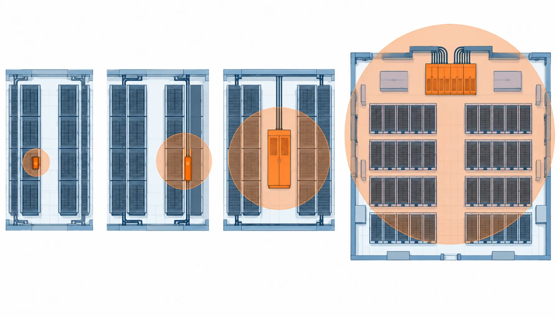
Where the distribution sits decides how much of the hall a fault can take out, and how much flexibility you retain when the rack plan changes. The comparison below is the one that belongs in the design review.
| Form Factor | What You Buy | What Must Be Specified | Cost and Lead Time | Failure Domain and Risk |
|---|---|---|---|---|
| In-rack unit | A compact unit inside the rack taking one DC feed and splitting it to branches | Branch DC rating, metering accuracy, thermal limits inside the enclosure | Lower unit cost, higher count, standard lead times | Smallest failure domain, but the unit itself sits in the hottest space |
| Rack-side unit | A side-mounted unit serving one or two racks, fed directly from the busway | DC branch protection, insulation monitoring, telemetry, IP rating | Mid cost, fewer units, growing supply base | One unit per rack pair, so a failure costs that pair |
| Row-level unit | A cabinet serving a row of racks over short DC feeders | Row current rating, coordination across branches, spatial footprint | Higher unit cost, fewer units, but consumes floor or aisle space | A failure takes out the whole row unless a bypass is bought with it |
| Hall or room level | Centralised distribution feeding rows over longer runs | Long-run voltage drop, protection coordination across the hall | Lowest equipment count, highest cable volume | Widest failure domain and the hardest coordination problem |
Protection: The Part That Genuinely Changes
An AC branch breaker is a mature commodity and the selection process is routine. A DC branch device at 800V is the item with the longest lead time in the whole distribution layer, and it is the one most often specified by habit rather than by duty. The central parameter is the circuit time constant: a DC breaking capacity quoted without it cannot be checked against the installation, because the same device performs differently as the inductance in the fault loop rises.
That has a direct consequence for PDU specification. A PDU is only as good as the devices inside it, so the branch device type has to be named in the enquiry rather than left to the manufacturer’s standard fit. Where the installation uses DC-rated breakers from a specific manufacturer, the PDU has to be built to accept them, and where the manufacturer fits its own device, the DC rating and its test basis have to be documented.
Coordination matters more here than in AC halls, because the PDU is the layer where selectivity is decided. The question is whether a fault on one branch takes out that branch or the upstream feed, and the answer depends on how the PDU’s devices coordinate with whatever sits upstream. That study has to be commissioned alongside the equipment rather than run at commissioning. Our note on the data center power chain shows where these layers sit relative to each other.
Metering a DC Circuit Is Not the Same as Metering an AC One
AC metering is straightforward because the quantity of interest can be sensed inductively — a current transformer around the conductor gives a usable signal without interrupting anything. Measuring direct current accurately at these levels generally means a shunt, a Hall effect sensor or a fluxgate arrangement, each with different accuracy, isolation and thermal characteristics. The choice affects the accuracy you can claim, the losses the metering introduces, and where the metering can physically sit.
For procurement the practical implications are three. Ask for the accuracy class and the measurement range, expressed at the currents the rack actually runs at rather than only at full load. Ask what the metering introduces in terms of losses and heat inside the enclosure. And ask how the data reaches your monitoring system, because a PDU that measures well and reports badly produces the same operational outcome as one that does not measure at all.
The monitoring question has a second half that matters on an unearthed DC system. A single ground fault does not trip, which is by design, so the fault is discovered by insulation monitoring rather than by a breaker. If the PDU is the natural place for that monitoring to live, the specification should say so, including the alarm thresholds and what the operations team is expected to do when one appears. A monitoring device whose alarms nobody owns is not a monitoring device.
Where the PDU Meets the Rest of the Power Path
A DC PDU does not exist on its own. It sits between the busway or cable feeding the row, the rack-level conversion or the server power input, and the monitoring system watching the whole hall. Each interface is a place where a specification gap becomes a site problem.
On the upstream side, the interface is the tap-off or the feeder from the distribution layer, and the question is who owns the connection hardware and its DC rating. On the downstream side, the interface is the rack-level converter shelf, and the question is whether the PDU’s impedance and protection settings were selected with that converter’s inrush and fault behaviour in mind. Both belong in the enquiry, and neither is answered by a PDU datasheet alone.
There is also a physical question that becomes real at these currents: what the PDU mounts to and how it is cooled. Row-level units consume aisle space that the layout may not have, and rack-side units add heat where the rack thermal design was already tight. In a hall built from modular or containerised capacity, the PDU arrangement also has to match the module’s internal layout rather than being designed from scratch — our containerised data center range is the conventional reference for how that integration is handled.
What to Freeze Before the DC PDU Order
Each item below is a place where a manufacturer will apply a standard fit unless the enquiry names what it wants.
| Specification Item | What to State | Evidence to Demand | Cost of Leaving It Open |
|---|---|---|---|
| Branch DC protection | Device type, DC rating and the circuit time constant it must break at | DC breaking test reported at that time constant | A branch that cannot clear a DC fault when asked to |
| Coordination and selectivity | The upstream device and the discrimination target for a branch fault | Coordination study and settings schedule | A single branch fault that takes out the whole row |
| Metering accuracy | Accuracy class and range, stated at the currents the rack actually runs at | Calibration certificate and the sensing method used | Energy and load data that cannot be relied on for decisions |
| Metering losses and heat | The loss the sensing method introduces, and its contribution to enclosure heat | Loss figures at rated current | A distribution unit that adds heat to an already tight thermal budget |
| Insulation monitoring | Device, alarm thresholds and the response procedure for an unearthed system | Scheme drawing and device data | A ground fault that nobody sees and nobody owns |
| Telemetry interface | Protocol, point list, update rate and integration method | Interface documentation and a point list | Metering that exists and is never used |
| Environmental rating | IP rating and ambient inside the mounting location | Test certification for the stated class | Condensation or coolant mist inside a live distribution unit |
| Mounting and access | Mounting arrangement, clearances, and how branches are reached for maintenance | Outline drawing and a serviceability statement | A unit that fits the drawing and cannot be worked on |
When a DC PDU Is Not the Right Purchase
DC distribution at rack level is the right answer for dense AI halls on a DC roadmap. It is the wrong answer in three familiar situations.
Moderate density halls. Below roughly 100 kW per rack the current levels do not justify DC protection, the AC PDU is a mature multi-source purchase with short lead times, and the metering problem does not exist because an AC current transformer does the job. The AC arrangement and its form factor trade-offs are covered in our note on rack and floor mounted PDUs.
Halls whose layout is still changing. A row-level DC distribution unit is a physical commitment to a rack plan. Where the plan is still moving, in-rack or rack-side units preserve flexibility at the cost of a higher unit count, and that premium is usually cheaper than moving a row cabinet that has already been installed and commissioned.
Facilities with no route to DC branch protection on schedule. The branch device is the longest-lead item in this layer. A hall that must energize before those devices can be supplied is better served by staying on AC distribution for the phase being built, with the distribution layer rated ahead so the later change is a rack-level swap. The expansion side of that planning is covered in our note on data center expansion cabling.
The mistake to avoid is buying a DC PDU as though it were an AC PDU with a different label. The connectors are the least of it. The protection device has a harder job, the metering needs a different sensing method, and the form factor decides how far a fault travels — and all three are decided in the specification, not in the catalogue.
RFQ Checklist for a DC PDU Package
Send the fault duty, the load profile and the mounting conditions. Each enquiry should carry:
- DC voltage class, and the voltage the system is energized at during this phase
- Current per rack and per feed, and the load profile the metering must cover
- Prospective fault current and the circuit time constant at each branch device
- The upstream device the PDU must coordinate with, and the discrimination target
- Metering accuracy class, range, sensing method, and the losses it introduces
- Telemetry protocol, data points, update rate and the monitoring system it feeds
- Insulation monitoring requirements, alarm thresholds and the response procedure
- Mounting location, clearances, IP rating, and the ambient inside it
- Cooling arrangement and the heat the unit contributes to the space
- Environmental and safety certification for the destination market, applied to the assembly
- Spares position for branch devices and metering components, with delivery dates
Conclusion
A DC PDU is a small cabinet doing three jobs that are all harder in direct current than in alternating current. It protects branches with devices that have to force an arc out, it meters current with sensing that cannot simply be wound around a conductor, and it defines the boundary inside which a fault is contained. Where that boundary sits — in the rack, beside the rack, at the row, or at the room — is the decision that shapes both the budget and the availability of the hall.
Specify it by naming the branch device and its time constant, demanding metering accuracy at the currents the rack actually runs at, and writing down who owns the telemetry and the insulation alarms. Kexingyu Cable Group (KXYE) supplies the distribution cabinets, busbar tap-off hardware and switchgear that these arrangements are built around — including the GGD power distribution cabinet and PZ30 distribution board ranges — together with the power, control and mineral insulated cable ranges used across these halls: WDZ-YJY, WDZN-YJY, BTTZ, BBTRZ, NG-A (BTLY), KVV and YJV, from a single factory group, with copper price linkage available on project-scale orders. Send your fault level, rack current and mounting arrangement and we will return a distribution schedule with the evidence list attached; the fastest start is a request for quotation.


