
Cable Reels and Port Cranes: Heavy-Duty Motion Applications Explained
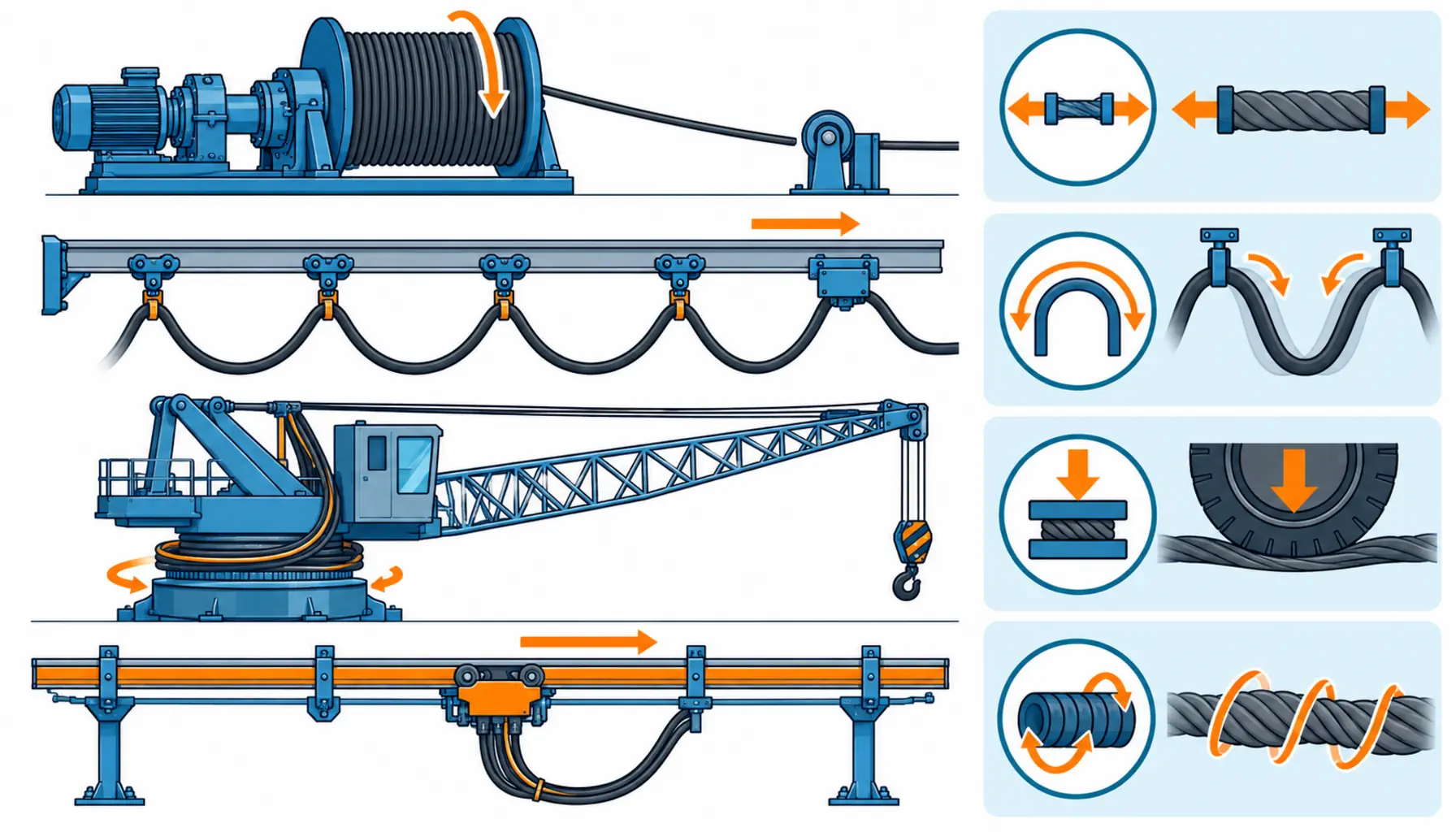
Quick Answer: Reeling and crane duty stacks winding, bending, tension and often torsion onto one cable — the hardest motion application in industry, demanding purpose-built reeling constructions and honest duty data from day one.
Stand under a ship-to-shore crane and watch the cable reel follow the trolley back and forth, winding and unwinding a hundred meters of heavy power cable through every cycle. Nothing in the cable’s world is gentle here: it is pulled under tension by a motorized drum, bent around the reel, wound onto itself layer after layer, and exposed to harbor weather and salt air while doing it. This is the heavyweight division of motion cable — larger conductors, harsher loads, and consequences measured in port throughput. A failed reeling cable does not idle one machine tool; it takes a crane out of the terminal’s critical path. This guide explains the heavy-duty motion applications that use reels, festoons and conductor rails, what those systems demand from the cable, and how to specify one that survives its duty instead of becoming the terminal’s recurring line item.
Introduction
Heavy-duty motion cable serves a family of machines that share one trait: the cable itself is part of the machine’s structure. Motorized cable reels on cranes and hoists, festoon systems on runways and trolleys, reeling drums on stacker-reclaimers and ship unloaders — in each case the cable is wound, tensioned, bent and sometimes twisted as a designed condition of operation, not an installation accident. The cable carries serious power too: crane duty cycles draw real megawatt-class loads, and at the longer travels the feed is medium voltage, which pulls reeling cables into the territory of MV cable standards and testing on top of every mechanical requirement.
The engineering consequence is that a reeling cable is a system component, not a purchase. It is specified together with the reel or festoon hardware, the tension control, and the duty profile of the machine. Buying a good cable into a badly engineered reeling system — or the reverse — produces the same outcome: a cable that fails in the same spot on every cycle until someone finally studies the system instead of the parts.
The Heavy-Duty Motion Applications, One by One
Each application in the crane family loads the cable differently, and the differences drive the design. Getting the application named correctly in the specification is half the battle.
| Application | How the Cable Moves | Loads on the Cable | Typical Machines |
|---|---|---|---|
| Motorized reeling drum | Cable winds and unwinds onto a powered drum following the machine | Tension from the drum motor, bending at the drum, layer crushing on the reel | STS cranes, hoists, stacker-reclaimers, cable cars |
| Festoon system | Cable hangs in loops between trolleys riding a track | Repeated looping at the saddle, sag weight, trolley acceleration | Overhead cranes, runway feeds, conveyor systems |
| Torsion reeling | Cable follows a rotating or slewing machine and twists as it travels | Torsion combined with winding, tension and bending | Deck cranes, slewing cranes, offshore equipment |
| Conductor rail (comparison) | Collector shoes slide on a rigid rail instead of a moving cable | Contact wear only — no cable motion | Long runway systems, terminals with fixed paths |
What Reeling Duty Demands From Construction
Reeling cable is built from the drum outward. The conductor stranding is fine and flexible, sized not only for ampacity but for the repeated bending at the drum — a rigid conductor work-hardens and breaks where a flexible one distributes the stress. Insulation and sheath layers are arranged to share the mechanical load: many reeling designs interleave strength members so the drum’s tension lands on the cable’s structure rather than the copper. Outer sheaths are thick, abrasion-resistant compounds — some reeling cables carry woven or spiral reinforcements over the sheath — because the cable slides against guides, the drum flange and its own wound layers all day.
Torsion is the load case that separates real reeling cable from flexible cable with a heavy jacket. When the machine travels and rotates — a deck crane slewing while its reel pays out — the cable accumulates twist. A construction that cannot distribute torsion will kink, and a kinked reeling cable is finished: the kink concentrates every subsequent load, and failure follows within cycles. Torsion-balanced designs use lay directions and layer arrangements that cancel twist instead of accumulating it. The difference is invisible on a quote sheet and decisive on the machine, which is why the application — reeling with or without rotation — must be stated explicitly, the same way the torsion cable guide insists on stating degrees and cycles.
The Reel System Around the Cable
Half of reeling reliability is hardware behavior that the cable has to live with. Tension control matters first: the drum motor must pay out and take up with tension matched to the cable’s rating — too little tension lets the cable pile and crush itself on the drum, too much stretches the conductors and sheath. Level winding keeps each layer lying evenly, because crossed layers create the pressure points where sheaths wear through. Drum diameter sets the minimum bend radius, and the cable’s radius requirement must respect the drum with margin at every layer, including the innermost wraps where the radius is tightest.
End terminations complete the system. The termination at the drum’s slip-ring or junction box and the free end at the machine both anchor the full dynamic tension, and they fail early when treated as an afterthought — the transition-zone failure pattern documented in the cable failure catalog, at its largest scale. Proper strain relief at both ends, glands matched to the cable’s construction, and accessories specified for the load rather than the lowest price are part of the cable specification; the hardware checklist in the cable accessories review applies with double weight here.
Festoon, Rail, or Reel: Choosing the Feed System
Not every long-travel machine needs a reel. Festoon systems loop the cable between trolleys on a track: cheap, simple, tolerant of abuse, and limited by sag — long travels mean deep loops, and high speeds make the loops whip. Conductor rails move the wear from a cable to collector shoes on a rigid bar: excellent for very long runways with fixed paths, but they carry the installation’s aesthetics and footprint with them and handle only the circuits you run through the rail. Motorized reels pay out the longest travels at full power with the cable following the machine — at the highest system cost and the most demanding cable specification. The choice is a system decision trading travel length, speed, power level and budget, and it should be made before any cable is quoted, because each system pulls a different construction.
| Check | What to Pin Down | Why It Decides the Outcome |
|---|---|---|
| Application type | Reeling with or without rotation, festoon or rail — named explicitly | Torsion duty changes the construction fundamentally |
| Duty data | Travel, speed, cycles per day, load spectrum of the machine | Sets flex life, tension rating and layer-crushing exposure |
| Reel geometry | Drum diameter, winding length, level-wind behavior, inner wrap radius | Bend radius and crushing live here, not in the datasheet |
| Tension control | Drum motor torque profile matched to the cable's tension rating | Wrong tension destroys the cable from inside the reel |
| Electrical level | Voltage class, load current, voltage drop at full travel, MV testing if applicable | Long crane travels push feeds into MV territory |
| Environment | Outdoor exposure, salt air, temperature band, UV, abrasion points | Sheath compound and reinforcements follow the site, not the catalog |
When Reeling Cable Rules Are Not the Answer
Honesty about scope keeps this guide useful. Reeling constructions solve winding, tension and torsion on drums and festoons. They do not transfer to guided chain duty — a machine tool or robot chain needs the short-lay, low-friction constructions of drag chain cable, and reeling cable is too heavy and stiff for those chains. They are not the answer for free-looping short-stroke axes either, where continuous-flex designs hold their own natural bend without any delivery hardware. And the fixed installation behind the crane — feeders from the substation, the port’s distribution design, grounding and protection — is stationary power engineering governed by the standards behind industrial distribution planning, not motion cable rules. Name the application, and the right product family follows.
RFQ Checklist: What to Send the Cable Supplier
Put the machine’s full duty in writing before quotes come back:
- Application named precisely: reeling with or without rotation, festoon, or rail comparison done
- Machine data: travel, speed, cycles per day, load spectrum, expected service life
- Reel or festoon geometry: drum diameter, winding length, loop depth, trolley track profile
- Electrical data: voltage class, load current, voltage drop at full travel, MV test requirements
- Tension system: drum motor control, maximum and minimum cable tension in operation
- Environment: outdoor exposure, salt, temperature band, UV, known abrasion or crush points
- Proof and documentation: torsion and flex test data, batch traceability, spare length policy
Conclusion
Reeling and crane duty is the most demanding motion application a cable can be asked to face: tension, winding, crushing and often torsion, megawatt-class power, and harbor weather, all day, for decades. Machines that specify purpose-built reeling constructions against the real drum geometry and duty profile run their full service life; machines that hang a heavy jacket on standard cable meet their failure schedule instead. The specification discipline is the product here.
Kexingyu Cable Group (KXYE) supplies heavy-duty reeling and motion cable constructions — tension-balanced, abrasion-resistant, and tested against stated duty — for cranes, hoists and heavy machinery, with batch traceability and documentation to match. Describe your machine and reel geometry through the RFQ page, and we will quote the construction against the duty, not the catalog.


