
Industrial Power Distribution: A Complete Equipment Checklist
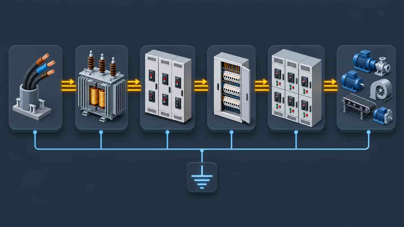
From the incoming supply to the last motor starter, a plant's distribution scope is finite and knowable—and forgetting an item on it is how projects stall at commissioning
Introduction
Industrial power distribution has an awkward property: the scope is entirely knowable, and yet equipment lists prepared from memory are consistently incomplete. The reason is that a plant’s electrical distribution is not a single product but a chain of items, each of which has its own ratings, its own protection requirements and its own interfaces. Miss one link—a neutral earthing arrangement, a cable sizing assumption, a metering class—and the gap is not discovered until the equipment is on site and the commissioning engineer asks for it.
The purpose of a checklist is therefore not administrative tidiness. It is to force the whole chain to be considered at quotation stage, when items can still be specified, priced and delivered together. The list below follows the electrical path from the incoming supply to the final load, names what belongs at each stage, and flags the items most frequently omitted. It is written for industrial plants—manufacturing, processing, mining, water treatment and similar facilities—where the loads are motors, drives, heating and process control rather than IT racks.
Read it as a specification framework rather than a product catalogue: for each line, the question is not only “do we need this equipment” but “what rating, what protection and what interface does it need to have to fit its neighbours.” For the wider equipment context, see our transformers and substations range.
How to Use This Checklist
Work through it in electrical order, and for each item record four things: the rating, the standard it must comply with, the protection that acts on it, and the interface it presents to the item downstream. Those four records are what turn a list of products into a coherent distribution design, and they are also what makes quotations from different suppliers genuinely comparable.
Two rules make the exercise considerably more valuable. First, record the fault level once and use it everywhere: switchgear, cables, transfer switches and protective devices all derive their ratings from the same prospective short-circuit current, and inconsistency here is one of the most common causes of a specification that cannot be built as written—our guide to choosing switchgear for a substation project works through what follows from that figure. Second, record the ambient and installation conditions for each area: temperature, altitude, humidity, dust, corrosive atmosphere and hazardous zone classification all change the equipment selected, and they vary across a plant in ways a single global assumption hides.
The Complete Equipment Checklist
| Stage | Equipment | Key Ratings to Fix | Often Forgotten |
|---|---|---|---|
| Incoming supply | Incoming breaker or switch-disconnector, protection relay, CTs and VTs, metering | Voltage, continuous current, fault level, protection functions, metering class | Metering class and relay function set; earthing arrangement of the supply |
| Step-down | Distribution transformer, earthing and neutral arrangement, surge protection | kVA, impedance, vector group, tapping range, cooling class, altitude and ambient derating | Vector group and neutral earthing method; surge arresters |
| Main distribution | LV main switchboard, busbar, incomer and bus-tie breakers, protection coordination | Busbar current, short-circuit withstand, IP rating, form of separation | Form of separation and IP rating; coordination study covering the whole board |
| Sub-distribution | Distribution boards, sub-main cables, isolation and switching devices | Board rating, outgoing device types, discrimination with upstream | Discrimination beyond the first level; neutral sizing on harmonic-rich loads |
| Motor control | MCC, starters or soft starters, variable speed drives, motor protection | Motor kW and starting method, duty cycle, drive harmonic impact, protection type | Harmonic impact on the supply; drive cooling and cable screen earthing |
| Power factor and quality | Capacitor banks or active compensation, harmonic filters, voltage stabilisation | kVAr requirement, harmonic spectrum, detuning, switching method | Harmonic study; detuned reactors where drives dominate |
| Continuity | UPS for control and critical loads, transfer switches, standby generator interface | Critical load list, transfer time, generator step-load acceptance | Defining which loads are genuinely critical; generator step-load check |
| Protection and control | Protective relays, interlocks, control and indication, SCADA or BMS integration | Protection scheme, protocol, alarm taxonomy, integration scope | Protocol and point list agreed before ordering; integration scope ownership |
| Earthing and lightning | Earthing system, equipotential bonding, lightning protection, SPDs by zone | Earth resistance target, electrode arrangement, SPD coordination by zone | SPD coordination between zones; bonding of structural steel and cable trays |
| Cabling and containment | Power and control cables, busway, trays and ladders, terminations and glands | Size, insulation, screen type, route, derating, termination compatibility | Derating for grouping and ambient; screen earthing at the drive end |
| Testing and documentation | FAT and SAT scope, protection settings record, as-built drawings, O&M and training | Test plan, acceptance criteria, language and format of documentation | Documentation language and format; spares list for commissioning spares |
The Items Most Often Left Off the List
Certain omissions recur across industrial projects regardless of sector, and they are worth naming explicitly because each one has a familiar consequence.
Neutral and earthing arrangement. The transformer’s vector group and its neutral earthing method determine how earth-fault protection behaves throughout the plant, yet they are frequently left to be decided at commissioning. Specifying them at design stage costs nothing; changing them later affects protection settings across the whole installation.
Harmonic impact. A plant that adds variable speed drives without a harmonic study can find its capacitor bank overheating, its transformer running hot and its protective devices misbehaving. If drives dominate the load, the compensation equipment needs detuned reactors or an active solution, and the study belongs in the original specification rather than in a later retrofit.
Derating factors. Cable sizes calculated at nominal ambient and single-circuit installation regularly fail once grouping, tray stacking, high ambient or altitude are accounted for. The correction factors are standard engineering; they are simply forgotten when the schedule is built from nameplate currents alone. The sizing method itself is set out in our guide to choosing the right cable size for an industrial project.
Generator step-load behaviour. Where a standby generator backs critical plant loads, the largest motor start and the simultaneous reconnection of the non-essential load determine whether the generator accepts the load or trips. This calculation often arrives too late, after the generator has been purchased on a total kW rating alone.
Monitoring integration. Protection relays, drives, meters and motor protection devices each have their own communications capability, and gathering them into one plant monitoring system requires the protocol and point list to be agreed before ordering. Retrofitting integration is a slow, expensive exercise that a single clause in the specification can prevent.
Commissioning spares. Fuses, indicator lamps, spare relays, glands and terminations are trivial in cost and can stop a commissioning programme dead if unavailable. A commissioning spares list belongs with the equipment order.
Ratings, Standards and Compatibility
| Stage | Equipment | Key Ratings to Fix | Often Forgotten |
|---|---|---|---|
| Incoming supply | Incoming breaker or switch-disconnector, protection relay, CTs and VTs, metering | Voltage, continuous current, fault level, protection functions, metering class | Metering class and relay function set; earthing arrangement of the supply |
| Step-down | Distribution transformer, earthing and neutral arrangement, surge protection | kVA, impedance, vector group, tapping range, cooling class, altitude and ambient derating | Vector group and neutral earthing method; surge arresters |
| Main distribution | LV main switchboard, busbar, incomer and bus-tie breakers, protection coordination | Busbar current, short-circuit withstand, IP rating, form of separation | Form of separation and IP rating; coordination study covering the whole board |
| Sub-distribution | Distribution boards, sub-main cables, isolation and switching devices | Board rating, outgoing device types, discrimination with upstream | Discrimination beyond the first level; neutral sizing on harmonic-rich loads |
| Motor control | MCC, starters or soft starters, variable speed drives, motor protection | Motor kW and starting method, duty cycle, drive harmonic impact, protection type | Harmonic impact on the supply; drive cooling and cable screen earthing |
| Power factor and quality | Capacitor banks or active compensation, harmonic filters, voltage stabilisation | kVAr requirement, harmonic spectrum, detuning, switching method | Harmonic study; detuned reactors where drives dominate |
| Continuity | UPS for control and critical loads, transfer switches, standby generator interface | Critical load list, transfer time, generator step-load acceptance | Defining which loads are genuinely critical; generator step-load check |
| Protection and control | Protective relays, interlocks, control and indication, SCADA or BMS integration | Protection scheme, protocol, alarm taxonomy, integration scope | Protocol and point list agreed before ordering; integration scope ownership |
| Earthing and lightning | Earthing system, equipotential bonding, lightning protection, SPDs by zone | Earth resistance target, electrode arrangement, SPD coordination by zone | SPD coordination between zones; bonding of structural steel and cable trays |
| Cabling and containment | Power and control cables, busway, trays and ladders, terminations and glands | Size, insulation, screen type, route, derating, termination compatibility | Derating for grouping and ambient; screen earthing at the drive end |
| Testing and documentation | FAT and SAT scope, protection settings record, as-built drawings, O&M and training | Test plan, acceptance criteria, language and format of documentation | Documentation language and format; spares list for commissioning spares |
The purpose of collecting this evidence at order stage is that it exposes incompatible assumptions while they can still be corrected. A transformer whose impedance is stated as a range cannot be coordinated properly; a relay whose point list arrives after ordering cannot be integrated without delay; a drive whose harmonic data is absent cannot be assessed against the compensation scheme. Each of these is cheap to fix before the order and expensive after it.
Sizing and Load Assumptions
Behind every line on the checklist sit load assumptions that determine the ratings, and these deserve to be recorded as explicitly as the equipment itself. The connected load is not the demand load: diversity factors, duty cycles and simultaneity reduce the total a plant actually draws, and applying no diversity produces an oversized installation while applying an unrecorded one produces an undersized one. Demand calculations should state their assumptions so a reviewer can challenge them.
Motor loads need special treatment because starting current dominates the design in a way that running current does not. Direct-on-line starting of a large motor imposes a voltage dip that may affect other loads on the same bus, and it determines the generator step-load requirement where standby power is involved. Starting method—direct-on-line, star-delta, soft starter or drive—is therefore not merely a process preference but a distribution design decision with consequences upstream.
Growth allowance belongs in the same record. A plant that adds a production line in three years will need spare capacity in the switchboard, the transformer and the cabling route, and retrofitting capacity into a tightly sized installation is far more expensive than allowing for it at design stage. The transformer capacity method behind that allowance is covered in how to choose transformer capacity for your project, and the size of the allowance itself should be a stated client decision rather than a supplier’s guess.
Conclusion
An industrial power distribution scope is finite, and the checklist above is close to a complete inventory of it. The value of working through it lies less in the list itself than in the discipline it imposes: fixing the fault level once, recording the fault level and ambient conditions per area, deciding the earthing and neutral arrangement at design stage, and collecting the evidence that proves each item fits its neighbours. Plants that do this build their distribution once. Plants that do not tend to build it twice.
For procurement, the practical benefit is comparability. A supplier given a complete checklist—with ratings, standards, interfaces and documentation requirements stated—can respond with a coherent package and a realistic schedule, rather than a price for a product they assume you want. KXY E-Power Group supplies transformers, switchgear, motor control, compensation equipment, cabling and the protection that connects them for industrial plants; send us your checklist, or ask us for ours, and we will respond at the level of ratings and interfaces rather than catalogue pages.
Frequently Asked Questions
Recent Posts

Voltage Stabilizers vs UPS: Do You Need Both?
Voltage Stabilizers vs UPS: Do You Need Both? One device fixes how high or low the voltage is; the other fixes whether there is voltage

Energy Storage for Data Centers: A Growing Backup Power Option
Energy Storage for Data Centers: A Growing Backup Power Option Batteries have always backed up data centers in the form of UPS strings. Grid-scale BESS
Thermal Runaway in Lithium Batteries: What BESS Buyers Should Understand
Thermal Runaway in Lithium Batteries: What BESS Buyers Should Understand How thermal runaway starts, how it propagates, and which evidence buyers should require before approving