
How to Choose Transformer Capacity for Your Project
Transformer capacity sizing starts with maximum coincident kVA—not the sum of every nameplate—and must also account for load profile, starting duty, harmonics, environment, redundancy and planned growth.
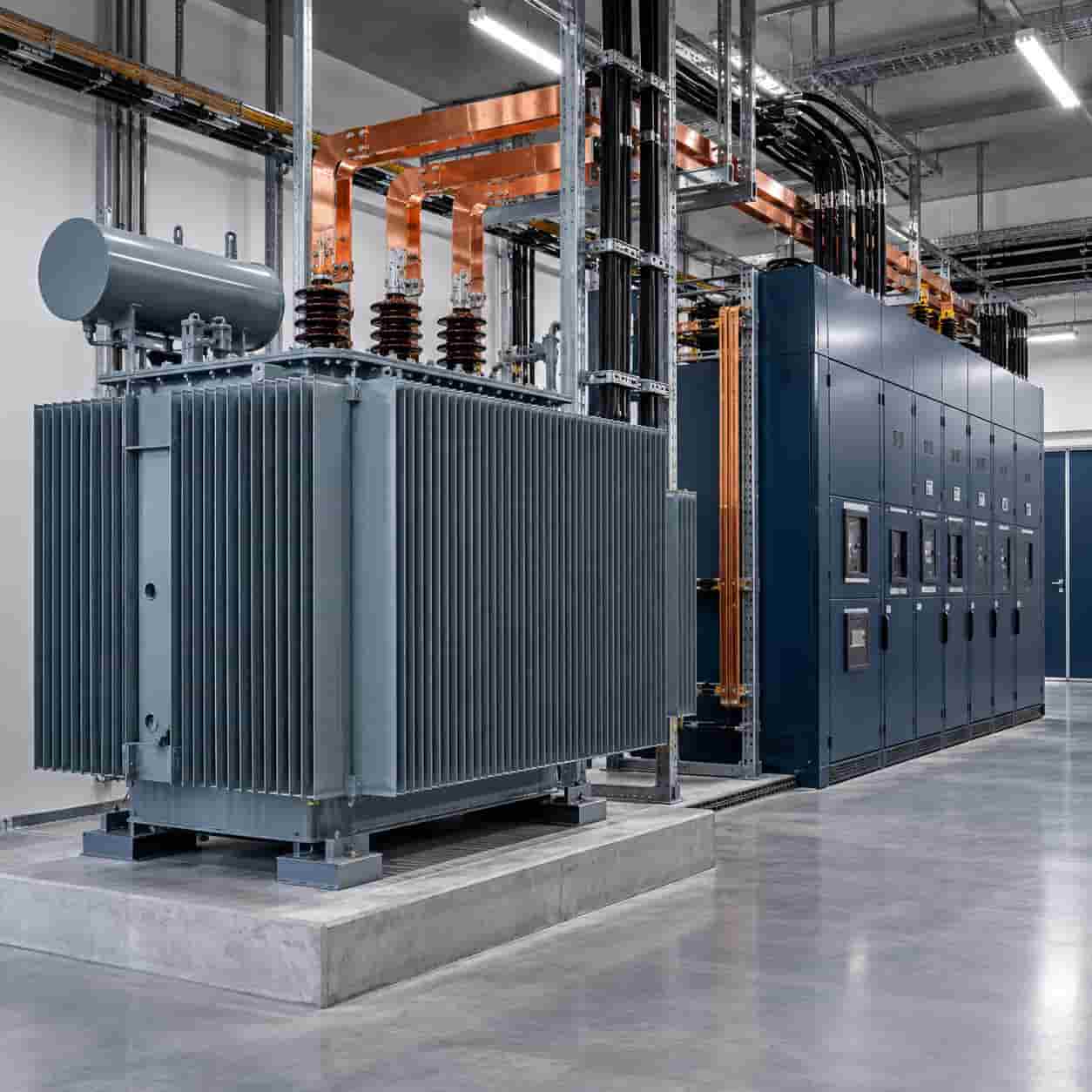
Introduction
Transformer capacity is normally stated in kVA or MVA because the windings and thermal design must carry current associated with both real power and reactive power. Choosing the rating from total connected kW alone can therefore be wrong in either direction.
A sound sizing process identifies the maximum coincident apparent-power demand, checks how long it lasts, and then tests starting duty, harmonics, ambient conditions, redundancy and growth. The final rating must also coordinate with cables, switchgear, protection and available fault current.
Start With the Right Load Data
Connected load is the sum of equipment nameplates. Maximum demand is the highest load expected to operate at the same time. Demand factor is the ratio between maximum demand and connected load, while diversity describes how individual peaks do not necessarily occur together.
For an existing facility, interval metering is usually more reliable than a generic demand factor. Review representative weekdays, weekends, seasons, production peaks and abnormal operating modes. Check whether the recorded period includes the load growth or process changes planned for the project.
For a new facility, build operating scenarios by load group: continuous, intermittent, standby, duty/standby, motor starting, electric heating, EV charging, UPS, HVAC and future phases. Document every simultaneity assumption so bidders calculate from the same basis.
Convert Real Power to Apparent Power
For a first-pass estimate, divide expected kW by power factor: kVA = kW ÷ PF. A 900 kW coincident load at 0.90 PF is 1,000 kVA. At 0.80 PF, the same 900 kW requires 1,125 kVA. This shows why power factor cannot be ignored.
For a balanced three-phase circuit, kVA = √3 × line-to-line voltage × line current ÷ 1,000. This equation checks electrical quantities, but it does not choose the transformer by itself.
Use the power factor expected at the relevant load case, not only a utility billing target. If capacitors or active correction are assumed, consider their availability, switching steps, harmonics and behavior at light load.
Use the Load Profile, Not One Peak Number
Transformer temperature depends on load magnitude, duration, starting temperature, ambient temperature and cooling. A five-minute peak does not have the same thermal effect as a ten-hour plateau, but it can still affect voltage regulation and protection.
IEC 60076-7 provides loading guidance for mineral-oil-immersed transformers from the perspective of operating temperature and thermal aging. IEC 60076-12 addresses dry-type transformer loading. Any planned loading above nameplate must be evaluated under the applicable guide and manufacturer data—not treated as free capacity.
Separate normal continuous duty, repetitive cyclic peaks, emergency duty and contingency duty. State which cases may consume insulation life and how often they are expected.
Check Motor Starting and Voltage Dip
Large motors may draw several times full-load current during starting. The actual current and duration depend on motor design, load torque and starting method such as direct-on-line, star-delta, soft starter or variable-frequency drive.
A transformer that carries the running load may still produce unacceptable voltage dip during a motor start. The study should include transformer impedance, upstream source strength, cable impedance, concurrent loads and the voltage tolerance of contactors, drives, controls and lighting.
Starting motors sequentially, changing the starting method or using a dedicated transformer can sometimes be better than simply increasing transformer kVA.
| Input | Why it affects capacity | Buyer data required | Common mistake |
|---|---|---|---|
| Maximum coincident demand | Defines the highest expected real operating load, not merely connected equipment. | Interval data, operating schedule or engineered demand calculation. | Adding every nameplate as if all loads run at full output together. |
| Power factor | Transformer rating is in kVA/MVA; lower power factor requires more apparent power for the same kW. | Expected operating and minimum power factor by load case. | Using kW as though it were kVA. |
| Load profile | Duration and repetition affect temperature rise and insulation aging. | 24-hour/seasonal curve, continuous base load and short peaks. | Treating a brief peak as continuous—or ignoring a long peak. |
| Motor starting | Starting current can cause voltage dip and thermal stress even when running kW is modest. | Motor size, starting method, sequence and permitted voltage dip. | Sizing only from full-load motor current. |
| Harmonics | Nonlinear currents increase winding and stray losses and may load the neutral. | Load mix, current spectrum/THDi and required K-factor or derating study. | Assuming simple oversizing removes harmonic distortion. |
| Site conditions | High ambient temperature, altitude, enclosure and cooling restrictions can reduce usable rating. | Temperature range, altitude, ventilation, cooling mode and enclosure. | Applying nameplate capacity without checking reference conditions. |
| Growth and redundancy | Future load and outage philosophy determine required headroom and unit arrangement. | Phased load forecast, N/N+1 strategy and permissible load shedding. | Adding an arbitrary margin without defining expansion or failure cases. |
Account for Harmonic Loads
UPS systems, data-center power supplies, EV chargers, VFDs, rectifiers and other nonlinear loads draw harmonic current. Harmonics can increase winding and stray losses, raise neutral current and create additional heating not represented by fundamental-frequency kVA alone.
A K-factor-rated or harmonic-duty transformer is designed to tolerate defined harmonic heating; it does not remove harmonics from the network. Depending on the system, the solution may include derating, phase-shifting, reactors, active filters, larger neutrals or equipment with lower current distortion.
Request the expected current spectrum or THDi and obtain a harmonic assessment. Do not select a K-factor from the industry label alone.
Apply Site and Cooling Conditions
Nameplate rating assumes declared service conditions. High ambient temperature, altitude, restricted ventilation, solar heating, enclosure design and blocked airflow can reduce cooling capability. Forced-air or pump-assisted ratings also depend on auxiliary equipment availability.
Indoor rooms need a heat-rejection calculation based on transformer losses and other equipment. Outdoor units require the correct environmental design for temperature, wind, pollution, corrosion, rain, snow, flood and solar exposure.
Confirm whether the manufacturer’s rating, temperature rise and guaranteed losses apply at the actual site altitude, ambient and cooling mode.
Plan Growth Without Arbitrary Oversizing
Future capacity should be tied to a dated load forecast: approved production lines, tenant phases, chargers, cooling equipment or data halls. An undefined percentage can either waste capital or prove insufficient.
Oversizing increases purchase cost, footprint, fault-current capability and often no-load losses. Undersizing can accelerate thermal aging, limit expansion and force an early outage for replacement. Compare staged transformers, modular substations or two-unit arrangements when growth is uncertain.
Redundancy Changes the Calculation
N+1 does not simply mean adding one arbitrary transformer. Define which load must remain after the largest unit or feeder is unavailable, whether noncritical load can be shed, and whether surviving units may operate at emergency loading.
Two transformers each loaded at 50% can provide full backup only if the switchgear, bus coupler, protection and cables can safely transfer the load and each unit can carry the contingency duty. Parallel operation also requires compatible ratio, vector group, impedance, tap position and system design.
Reliability studies should consider common-mode failures, maintenance isolation, spare strategy and restoration time—not transformer count alone.
A Practical Preliminary Sizing Example
Assume an engineered maximum coincident demand of 900 kW at 0.90 power factor. The initial apparent-power requirement is 900 ÷ 0.90 = 1,000 kVA.
If a documented near-term expansion adds 180 kW at a similar power factor and is expected to coincide, the preliminary demand becomes approximately 1,200 kVA. A standard rating above this value might appear suitable, but the engineer must still check motor starting, harmonics, ambient derating, load duration, voltage regulation and contingency duty.
This example is not a universal sizing rule. A site with high harmonic content, weak source voltage, severe temperature or mandatory N+1 operation may need a different rating or arrangement.
Information to Send With an RFQ
Provide primary and secondary voltage, frequency, phases, vector group, grounding, impedance target, tap range and short-circuit level. Attach the single-line diagram and protection philosophy.
Provide connected-load schedule, coincident demand calculation or metering data, load curve, power factor, motor list and starting methods, harmonic data, future phases, redundancy criteria and load-shedding plan.
Conclusion
Choose transformer capacity from maximum coincident kVA and the complete duty cycle—not connected kW or a generic spare margin. Power factor, motor starting, harmonics, site conditions, growth and redundancy can materially change the result.
A documented load model makes supplier offers comparable and prevents hidden assumptions. Final selection should be confirmed by the project electrical engineer through load-flow, voltage-drop, short-circuit, protection and thermal studies.
Frequently Asked Questions
For an initial estimate, apparent power is kVA = kW ÷ power factor. For a balanced three-phase circuit, kVA = √3 × line voltage × line current ÷ 1,000. Final selection still requires demand, load profile, starting, harmonics, environment and redundancy checks.
Use maximum coincident demand as the main operating basis, supported by measured interval data or a defensible demand calculation. Connected load remains useful for checking possible future operation, but assuming every item runs fully at once often oversizes the transformer.
There is no universal percentage. Headroom should be linked to a dated load-growth forecast, approved future equipment and operational flexibility. Too little can force early replacement; excessive spare capacity raises capital cost and may increase no-load losses.
They may. Motor starting can create high current and voltage dip even when running demand is acceptable. The study should include motor size, starting method, starting sequence, source impedance and the voltage dip tolerated by other loads.
Nonlinear loads can increase winding, eddy-current and neutral heating. The solution may involve a K-factor or harmonic-duty transformer, derating, harmonic mitigation or another engineered design. Oversizing alone does not remove voltage or current distortion.
The answer depends on reliability, maintenance, load growth, efficiency at partial load, fault level, switchgear arrangement and cost. Two units can support redundancy or phased loading, but the required surviving capacity and allowable load shedding must be defined.
Recent Posts
Energy Storage for Data Centers: A Growing Backup Power Option
Energy Storage for Data Centers: A Growing Backup Power Option Batteries have always backed up data centers in the form of UPS strings. Grid-scale BESS
Thermal Runaway in Lithium Batteries: What BESS Buyers Should Understand
Thermal Runaway in Lithium Batteries: What BESS Buyers Should Understand How thermal runaway starts, how it propagates, and which evidence buyers should require before approving
Switchgear Lead Times in 2026: A Buyer’s Planning Guide
Switchgear Lead Times in 2026: A Buyer’s Planning Guide Realistic timelines vary significantly by voltage class and type — here’s how to plan procurement without