
Control Cable vs Instrumentation Cable: What's the Difference?
Two cable types that often sit in the same panel but serve very different purposes — here's how to tell them apart and specify each correctly.
Introduction
Control cable and instrumentation cable often end up in the same panel, run through the same cable trays, and get specified by the same engineer on the same drawing — which is probably why the two terms get used interchangeably more often than they should. They’re built for different jobs, and mixing them up in a specification can cause real problems, particularly around signal reliability.
What control cable is designed for
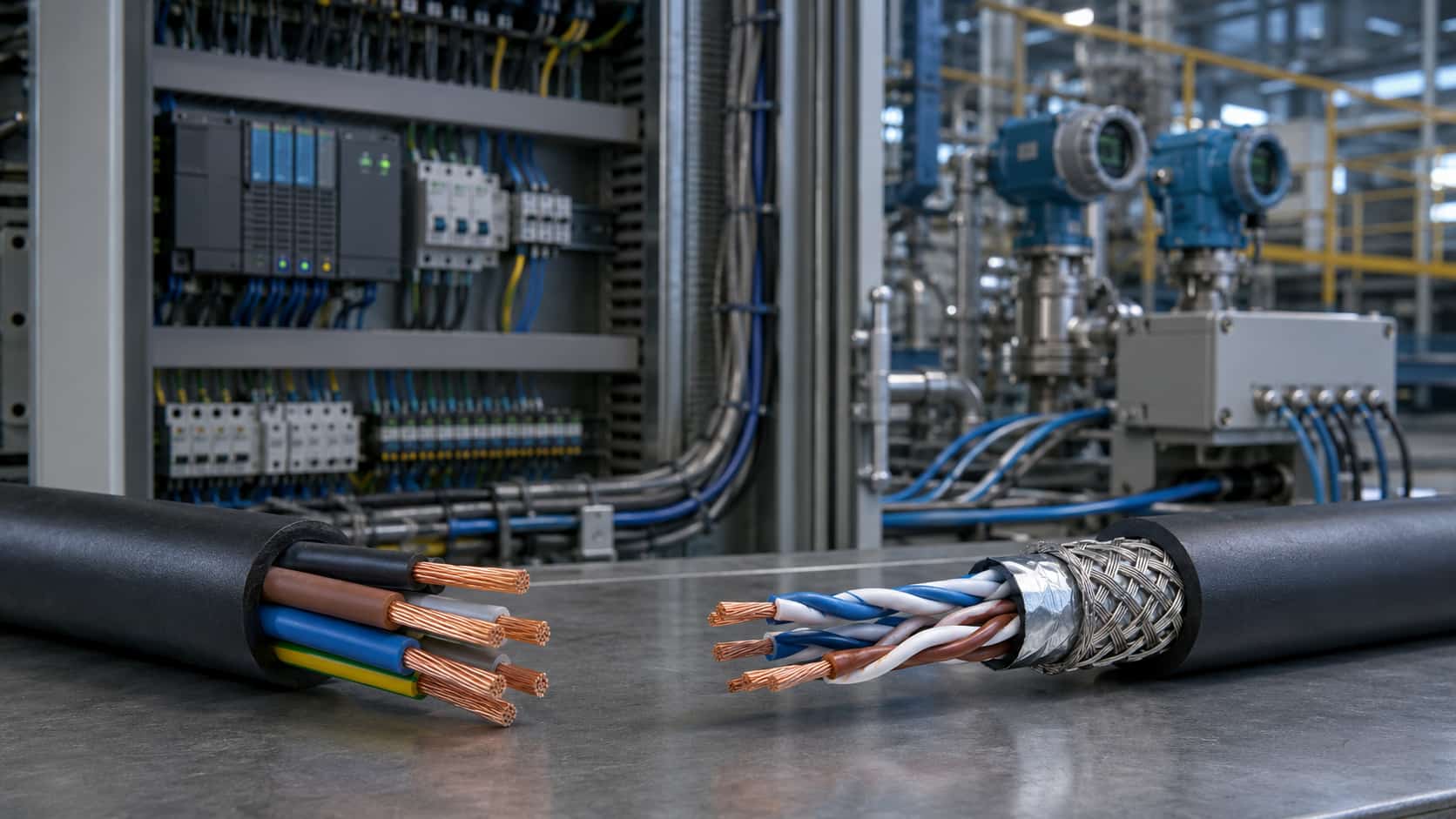
Control cable carries power or switching signals to operate equipment — think motor starters, relays, solenoids, and control panel wiring. It’s typically multi-core, moderate gauge, and designed to reliably carry a switching current or control voltage over relatively short distances within a facility. Signal integrity in the sense of preserving a precise, low-level analog or digital signal generally isn’t the primary design concern for standard control cable.
What instrumentation cable is designed for
Instrumentation cable carries low-level signals from sensors, transmitters, and measurement instruments back to a control system — signals that are often analog (4-20mA current loops, for example) or low-voltage digital, and highly sensitive to electrical noise. Because these signals can be easily corrupted by electromagnetic interference from nearby power cable, instrumentation cable is built around signal integrity first.
Key construction differences
Instrumentation cable is almost always shielded — using a foil or braided shield layer to block electromagnetic interference — and frequently uses twisted pair construction, which further cancels out induced noise. Control cable is typically unshielded unless the specific application calls for it, and uses straight multi-core construction rather than twisted pairs, since it isn’t carrying signals sensitive to the same noise issues.
Voltage and current differences
Control cable typically operates at standard control voltages (24V, 110V, 230V AC or DC depending on the system) and carries enough current to actually operate a relay coil or contactor. Instrumentation cable carries very low current, low-level signals — the electrical load is almost irrelevant compared to preserving signal accuracy over distance.
Where they're used together in the same panel
In a typical industrial control panel, control cable wires the switching and operational logic, while instrumentation cable brings in sensor readings that logic depends on — temperature, pressure, flow, level. Running these two cable types too close together in the same tray without adequate separation is a common cause of signal interference issues, which connects to the broader topic covered in our cable failure causes guide — interference-driven signal errors are a subtler failure mode than a cable physically breaking down, but just as disruptive to operations.
Common specification mistakes
Using unshielded control cable for a genuinely sensitive instrumentation signal, routing instrumentation cable in the same tray as high-current power or control cable without separation, and specifying instrumentation cable without confirming shield grounding requirements are among the most common and avoidable mistakes on industrial projects.
Where Kexingyu Power fits in
We manufacture both control and instrumentation cable, with shielded and unshielded options built to project-specific requirements. Browse the full range on our Cables & Wiring Systems page.
Control vs Instrumentation Cable
Common questions from engineers and project buyers specifying control, instrumentation and signal cables for industrial automation systems.
01 Can instrumentation cable be used for control wiring?
It may be technically possible when the conductor size, voltage rating and installation requirements are suitable, but it is often unnecessary. Instrumentation cable commonly includes twisted pairs and individual or overall shielding designed to protect low-level signals from interference. For ordinary control circuits, these additional features may increase cost without providing a practical benefit.
02 Should an instrumentation cable shield be grounded at one end or both ends?
The correct bonding method depends on the signal type, frequency, equipment design and grounding system. Single-end grounding is commonly used for low-frequency analog signals to reduce ground-loop current, while high-frequency or digitally controlled systems may require bonding at both ends. Follow the control-system designer's grounding plan and equipment manufacturer's instructions rather than applying one method to every circuit.
03 How much separation is required between power, control and instrumentation cables?
The required separation depends on power-circuit voltage and current, cable shielding, tray construction, route length and the sensitivity of the instrumentation signal. Low-level analog and communication circuits generally require greater protection from power cables, motor feeders and variable-frequency drive outputs. Use the separation distances and tray-dividing requirements stated in the project standard instead of estimating them on site.
04 Is twisted-pair construction used only for instrumentation cable?
No. Twisted-pair construction is widely associated with instrumentation cable because twisting helps reduce induced electromagnetic noise in signal circuits, but the same construction may also be used in communication, data and specialized control cables. It is a cable-design technique selected according to signal integrity requirements rather than an exclusive feature of one cable category.
Recent Posts
Voltage Stabilizers vs UPS: Do You Need Both?
Voltage Stabilizers vs UPS: Do You Need Both? One device fixes how high or low the voltage is; the other fixes whether there is voltage
Energy Storage for Data Centers: A Growing Backup Power Option
Energy Storage for Data Centers: A Growing Backup Power Option Batteries have always backed up data centers in the form of UPS strings. Grid-scale BESS
Thermal Runaway in Lithium Batteries: What BESS Buyers Should Understand
Thermal Runaway in Lithium Batteries: What BESS Buyers Should Understand How thermal runaway starts, how it propagates, and which evidence buyers should require before approving