
How to Read a Switchgear Single Line Diagram (SLD)
A plain-language walkthrough of the symbols and conventions that show up on almost every switchgear specification drawing.
Introduction
A single line diagram — often just called an SLD — is one of the most common drawings you’ll encounter when specifying or reviewing switchgear, and it’s designed to be read even without a full electrical engineering background, once you know the basic symbol conventions. If you’re new to switchgear terminology generally, our switchgear basics guide is a useful starting point before this one.
What a single line diagram actually is
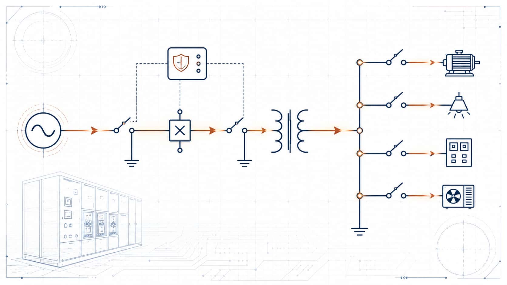
An SLD represents a three-phase electrical system using a single line, rather than drawing out every individual phase conductor — hence the name. It’s a simplified schematic showing how power flows from source to load through the major equipment in between, without the full physical wiring detail of a construction drawing.
Basic symbols you'll encounter
A circuit breaker is typically shown as a small square or rectangle on the line, sometimes with an X or specific breaker symbol inside. A disconnector or isolator switch appears as a diagonal line crossing the main line, representing an open-air disconnect point rather than a load-breaking device. A transformer is usually drawn as two overlapping circles, representing the primary and secondary windings. A busbar is drawn as a thick horizontal or vertical line that multiple circuits connect to, representing the common distribution point. Protection relays are often shown as small circles with a letter code indicating the specific protection function.
How to trace power flow through an SLD
SLDs are typically drawn top-to-bottom or left-to-right, following the direction power actually flows — starting from the utility connection or generation source, through transformers and switchgear, down to the individual loads at the bottom or right side of the drawing. Following the main line from source to load is usually enough to understand the overall system structure before drilling into individual component details.
What voltage and rating labels tell you
Most SLDs label key points with voltage (before and after a transformer, for example), current or capacity rating for major equipment, and sometimes fault current levels at critical points. These labels are what actually make the diagram useful for specification purposes — the symbols show what type of equipment is present, and the labels show what rating it needs to be.
Common SLD conventions
A normally open point in a system — often at a bus tie between two sections that can be connected for backup but usually run independently — is typically shown with a specific symbol or annotation distinguishing it from a normally closed connection. Understanding which connections are normally open versus closed is important for correctly interpreting how the system actually operates day-to-day versus during a backup or maintenance scenario.
Why SLDs matter when ordering switchgear
The SLD is often the primary reference document a switchgear manufacturer works from to confirm your specification — voltage class, breaker ratings, and busbar configuration should all be traceable directly from the diagram. This connects directly to decisions like the LV vs MV boundary in your system, which should be clearly represented on the SLD at the transformer connection point.
Where Kexingyu Power fits in
Our technical team can review your project’s SLD directly to confirm switchgear specifications before manufacturing begins. Browse the full range on our Switchgear & Distribution page.
Reading Single Line Diagrams
Common questions from project buyers and facility managers learning how to read and use electrical single-line diagrams for the first time.
01 Do I need engineering training to understand a basic single-line diagram?
Not for a general understanding. Most buyers can learn to follow the main power path from the utility or generator source through switchgear, transformers and distribution equipment to the connected loads. Recognizing common equipment symbols and voltage levels is usually enough for basic project discussions. Detailed fault-current, protection-coordination and equipment-rating decisions should still be reviewed by a qualified electrical engineer.
02 Are single-line diagram symbols standardized internationally?
Many electrical symbols follow recognized IEC, IEEE, ANSI or other regional drafting conventions, but the exact appearance and notation can vary between countries, engineering consultants and individual projects. Always check the drawing legend, abbreviations and project notes before interpreting an unfamiliar symbol rather than assuming every SLD uses exactly the same graphical convention.
03 Is a single-line diagram the same as a wiring diagram?
No. A single-line diagram provides a simplified overview of the electrical system, showing major equipment, feeders, voltage levels, protection devices and the relationship between system sections. Wiring diagrams provide much more detailed connection information, including individual control wires, terminals, contacts and device connections needed for manufacturing, installation or troubleshooting.
04 Can a switchgear manufacturer prepare a quotation from an SLD alone?
An SLD is often sufficient for a preliminary quotation when it clearly shows the incoming supply, bus arrangement, feeder quantity, major equipment and basic ratings. A final technical offer normally requires additional information such as rated voltage and current, short-circuit level, protection requirements, metering, enclosure rating, cable entry direction, installation environment, applicable standards and any communication or interlocking requirements.
Recent Posts

Power Cable Warranty Terms: What to Demand and What to Watch For
Power Cable Warranty Terms: What to Demand and What to Watch For Quick Answer: A usable warranty names its scope, duration, evidence standard, exclusions and

The Cable Sample Approval Process: What to Test Before Mass Production
The Cable Sample Approval Process: What to Test Before Mass Production Quick Answer: Sample approval tests the supplier’s claims while changes are still cheap —

Cable Drum Packaging for Export: Specs, Marking and Transit Protection
Cable Drum Packaging for Export: Specs, Marking and Transit Protection Quick Answer: Export packaging is a technical specification: drum size for weight and bend radius,