
Pad-Mounted vs Pole-Mounted Transformers: What's the Difference?
A practical comparison of installation, safety, maintenance, cost, and procurement requirements for underground and overhead distribution systems
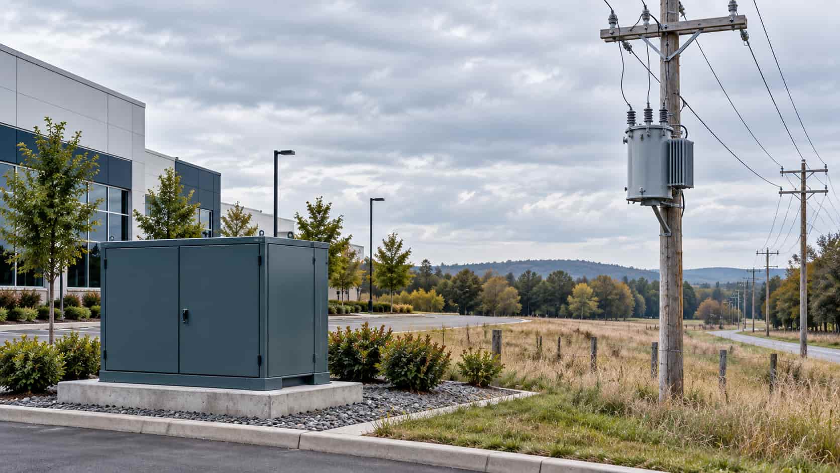
The main difference between a pad-mounted and pole-mounted transformer is not simply where the tank is installed. The mounting method reflects the distribution network around it. Pad-mounted transformers are generally designed for ground-level service from underground primary cables, while pole-mounted transformers are generally integrated into overhead distribution lines.
For a buyer, EPC contractor, or utility engineer, the correct choice depends first on the existing or planned network. Installation cost, public safety, maintenance access, environmental exposure, cable or conductor interfaces, and local utility rules then determine whether the selected arrangement is practical. A lower transformer price does not necessarily produce a lower installed project cost.
Pad-Mounted vs Pole-Mounted Transformer: Quick Answer
Choose a pad-mounted transformer when the primary distribution is underground, the project can reserve an accessible ground-level equipment area, and the required cable terminations, feed arrangement, enclosure security, drainage, and vehicle protection can be provided.
Choose a pole-mounted transformer when the primary distribution is overhead, the required capacity and equipment weight are compatible with the pole structure, statutory clearances can be maintained, and qualified crews can safely install and maintain the equipment using climbing or aerial-lift methods.
This is a system decision. Transformer capacity, voltage, impedance, losses, and insulation requirements still need to be engineered independently. If sizing is not complete, review our guide to transformer capacity sizing before requesting final quotations.
What Is a Pad-Mounted Transformer?
A pad-mounted transformer is a ground-level distribution transformer installed on an engineered concrete pad or other approved foundation. In common liquid-filled designs, the transformer tank and a lockable terminal cabinet form an integrated assembly. The cabinet shields cable terminations, bushings, switching points, fuses, and low-voltage connections from casual contact and weather exposure.
Pad-mounted units are common in residential developments, shopping centers, campuses, factories, renewable-energy balance-of-plant systems, and other locations where power distribution is routed underground. Depending on the utility architecture, the primary side may be arranged for radial feed or loop feed. Those configurations are not interchangeable purchase details: they affect bushings, switching, cable parking provisions, protection, operating procedures, and cabinet layout.
Ground-level installation makes inspection and service access easier than elevated equipment in many projects, but it transfers important responsibilities to the site design. The pad opening, conduit alignment, finished grade, drainage, soil conditions, equipment clearances, grounding, and protection from vehicles must all match the approved drawings and local requirements.
What Is a Pole-Mounted Transformer?
A pole-mounted transformer is installed above ground on a utility pole or engineered pole structure and connected to an overhead distribution circuit. Single-phase units often serve individual loads or sections of a low-voltage network. Multiple single-phase units may also be connected as a bank for a three-phase supply, subject to the utility’s standard arrangement and protection philosophy. Three-phase pole-mounted designs are also available in some markets and ratings.
The pole installation typically includes mounting brackets or a platform, primary cutouts or other protection, surge arresters, grounding conductors, secondary conductors, and associated line hardware. These items must be coordinated with the transformer rather than treated as generic accessories.
Pole-mounted equipment uses little ground area and is a natural fit for an existing overhead feeder. However, transformer mass, wind loading, conductor tension, other attachments, pole condition, and the installation method must remain within the structure’s design limits. Maintenance may require a bucket truck, traffic management, safe isolation, and specialized line crews.
Key Differences That Affect Project Decisions
| Decision Factor | Pad-Mounted Transformer | Pole-Mounted Transformer |
|---|---|---|
| Primary network | Usually underground primary cable; radial or loop-feed arrangements may be used | Usually overhead primary conductors; single unit or transformer bank |
| Location | Ground level on an engineered pad or foundation | Mounted on a utility pole or pole structure |
| Electrical access | Terminations and accessories inside a lockable compartment | Connections and protective devices elevated on the pole |
| Typical site fit | Urban, suburban, commercial, campus, and industrial sites with underground distribution | Rural, roadside, low-density, and established overhead networks |
| Civil or structural work | Pad, cable conduits, drainage, grading, grounding, working clearances, and vehicle protection where needed | Pole loading check, mounting hardware, lifting access, conductor clearances, grounding, and guying where required |
| Maintenance access | Ground-level access, but technicians need safe front working space and vehicle access | Usually requires climbing or an aerial lift and traffic/work-zone control |
| Exposure profile | More exposed to flooding, standing water, corrosion, landscaping interference, and vehicle impact | More exposed to wind, falling trees, lightning environment, pole damage, and vehicle collision with the pole |
| Public interface | Tamper-resistant enclosure and site barriers/clearances are important | Live parts are elevated, but the pole and down-ground remain public-facing assets |
| Aesthetics and right-of-way | Lower visual profile, although ground footprint must be reserved | Small ground footprint but visible overhead equipment and conductors |
| Procurement emphasis | Cable interface, feed arrangement, bushings, cabinet layout, pad opening, corrosion class, and accessories | Weight, pole strength, brackets, bushing arrangement, surge protection, cutouts, and lifting/installation method |
1. Network architecture and electrical interface
A pad-mounted transformer usually receives underground primary cable through the pad opening and uses separable insulated connectors or other specified cable terminations. A pole-mounted transformer connects to overhead conductors using exposed outdoor bushings and line hardware arranged at safe elevation. Converting between the two normally requires more than changing brackets: the transition equipment, protection, grounding, terminations, and utility operating scheme may all change.
For pad-mounted equipment, confirm radial versus loop feed, dead-front versus any permitted live-front arrangement, bushing interface, cable size and bend radius, parking stands, switching and fusing requirements, and the exact high-voltage/low-voltage compartment orientation. For pole-mounted equipment, confirm bushing orientation, arrester and cutout arrangement, bracket pattern, secondary terminals, conductor routing, and the pole’s structural allowance.
2. Site work and installation
Pad-mounted installation can require more civil work: foundation design, excavation, conduits, cable pulling, grounding, bollards where traffic exposure exists, and drainage or flood mitigation. The pad must remain level and support the operating mass without settlement that can distort the cabinet or cable interfaces.
Pole-mounted installation reduces the ground footprint but moves complexity into overhead work. The project may need a new or upgraded pole, guying, road closures, lifting equipment, outage coordination, and verification of electrical clearances. A unit that meets the electrical specification can still be unacceptable if its mass or dimensions exceed the pole and lifting constraints.
3. Public safety and security
A pad-mounted transformer is accessible at ground level, so a tamper-resistant enclosure, robust locking, correct compartment construction, and controlled clearances are fundamental. Landscaping must not obstruct doors or ventilation, and snow, debris, or storage must not block access. Vehicle protection may be required, but barriers must be positioned so they do not prevent door operation, cable work, or equipment replacement.
A pole-mounted transformer elevates energized components away from normal public reach. That does not eliminate risk: pole climbing, down-ground protection, conductor clearance, pole collision, vegetation, and work-zone control remain important. Safety performance depends on the complete installation and operating procedures, not mounting height alone.
4. Environmental exposure and resilience
Pad-mounted transformers can be vulnerable to floodwater, stormwater ponding, salt, fertilizers, irrigation spray, coastal corrosion, and vehicle impact. Site elevation, drainage, coating system, cabinet material, gasket design, and maintenance plan should reflect the actual exposure.
Pole-mounted transformers are more exposed to wind, falling branches, wildfire conditions, lightning environment, and damage to the supporting pole. In severe weather, neither mounting type is automatically resilient. Resilience comes from hazard-specific siting, protection, structural design, vegetation management, spares strategy, and restoration access.
5. Maintenance and replacement logistics
Ground-level equipment can often be inspected and accessed without climbing, but technicians still need safe working space, switching authority, cable identification, and a route for a service vehicle or crane. Cabinets, hinges, locks, seals, cable compartments, fluid condition, grounding connections, and signs of settlement or corrosion should be included in the maintenance program.
Pole-mounted equipment avoids ground-level obstruction but normally needs an aerial lift or qualified climbers. Replacement planning should consider truck position, traffic control, pole integrity, conductor handling, outage duration, and the availability of compatible mounting hardware.
6. Cost and lead-time drivers
The relevant comparison is total installed cost. For a pad-mounted system, include the transformer, primary and secondary cable, terminations, civil works, pad, grounding, barriers, testing, and future access. For a pole-mounted system, include the transformer, pole and structural upgrades, hardware, protection, arresters, conductors, lifting, line labor, traffic control, and outage work.
Lead time can also be driven by nonstandard voltages, unusually high insulation levels, low-loss requirements, special fluids, stainless-steel or enhanced corrosion construction, accessories, utility-specific interfaces, and approval drawings. Coordinate transformer and switchgear schedules early because one late interface decision can hold both packages.
How to Choose the Right Mounting Type
Step 1: Confirm the serving network
Obtain the utility’s point-of-connection requirements and determine whether the primary feeder is overhead or underground. If the project creates a transition between them, define who owns and approves the transition pole, cable, protection, metering, and transformer.
Step 2: Check site and access constraints
For a pad-mounted option, reserve the footprint, door swing, working clearance, cable route, drainage zone, and replacement path. For a pole-mounted option, verify right-of-way, statutory conductor clearances, pole loading, aerial-lift access, traffic impact, and the position of other utilities.
Step 3: Evaluate hazards
Record flood level, wind, seismic conditions, lightning exposure, salt or industrial contamination, ambient temperature, altitude, wildfire exposure, vandalism risk, vehicle movement, and fire-safety constraints. Do not use a generic outdoor rating as a substitute for this assessment.
Step 4: Compare life-cycle cost and operability
Include installation, energy losses, planned inspection, vegetation or site maintenance, access equipment, outage duration, spare-unit compatibility, repair capability, and end-of-life removal. Ask the operator which arrangement its crews can safely isolate, test, and replace.
Step 5: Freeze interfaces before production
Approve the general arrangement, nameplate schedule, terminal plan, foundation or mounting details, accessory list, protection interface, cable or conductor data, and test plan before manufacturing. Late changes to feed arrangement, bushing type, compartment orientation, or mounting geometry can require a substantial redesign.
Standards and Specification Notes
The applicable standard depends on the country, utility, voltage class, phase configuration, and product design. In North American practice, IEEE C57 standards address different categories of overhead and pad-mounted liquid-immersed distribution transformers. For example, IEEE C57.12.34 covers specified three-phase pad-mounted, compartmental-type transformers within its stated voltage and power limits; other C57 documents apply to single-phase pad-mounted, overhead, or different configurations.
In IEC-based markets, the IEC 60076 series provides the general transformer framework, with relevant parts addressing items such as general requirements, temperature rise, insulation levels and dielectric tests, short-circuit withstand, loading guidance for oil-immersed transformers, and sound levels. National deviations, utility specifications, efficiency regulations, environmental rules, and fire codes may add or supersede requirements.
Do not specify a standard number from a previous project without checking its scope and current edition. The purchaser should state the governing document hierarchy and identify which party resolves conflicts among the utility standard, project specification, national code, and manufacturer drawings.
RFQ Checklist for Pad-Mounted and Pole-Mounted Transformers
Electrical ratings: rated kVA; number of phases; frequency; primary and secondary voltages; connection or vector group; taps and tap-changer type; percentage impedance and tolerance; insulation level/BIL where applicable; temperature rise; cooling method; loss or efficiency limits; load profile; harmonic or special duty; parallel-operation requirements; and expected future loading.
Service conditions: indoor/outdoor designation; maximum and minimum ambient temperature; altitude; humidity; flood exposure; seismic, wind, salt, dust, or corrosive environment; fluid preference; fire-safety restrictions; noise limit and measurement basis; and required coating or enclosure material.
Pad-mounted interface: radial or loop feed; cable type and size; termination interface; bushing and parking provisions; switching and fusing; high-voltage and low-voltage compartment arrangement; cabinet security; pad opening and anchoring; door swing; accessories; metering; grounding points; and civil drawings.
Pole-mounted interface: transformer mass and dimensional limits; pole class and available loading; mounting bracket or platform; bushing layout; cutout and arrester arrangement; secondary terminal configuration; lifting points; grounding; conductor data; wildlife protection where required; and installation hardware responsibility.
Documentation and quality: applicable standards and edition; outline and approval drawings; wiring diagram; nameplate; guaranteed loss data; routine test report; any specified type or special tests; fluid documentation; material declarations; inspection points; packing method; transport dimensions and mass; installation manual; recommended spares; warranty terms; and deviation list.
Common Procurement Mistakes
Comparing only kVA and voltage. Two transformers with the same headline rating may have incompatible feed arrangements, terminals, impedance, insulation levels, losses, accessories, or dimensions.
Selecting the transformer before confirming the network. An underground project may require loop-feed features and cable interfaces that a basic quotation does not include. An overhead project may be constrained by pole loading before electrical design is complete.
Ignoring the replacement route. A pad-mounted unit boxed in by landscaping or walls, or a pole unit inaccessible to an aerial-lift truck, can turn a routine replacement into a long outage.
Assuming one mounting type is always safer or more reliable. Hazards differ. Flooding, vehicle impact, wind, vegetation, lightning, corrosion, vandalism, and crew access must be assessed for the actual site.
Leaving utility approval until after production. Utilities often control connection details, protection, metering, clearances, and equipment interfaces. Approval should be obtained before manufacturing drawings are released.
Conclusion
In a pad-mounted vs pole-mounted transformer comparison, the surrounding distribution system should lead the decision. Pad-mounted equipment is generally the practical match for underground networks and sites that can support secure, well-drained, ground-level installation. Pole-mounted equipment is generally the practical match for overhead networks where structural capacity, electrical clearances, and line-crew access are available.
A reliable procurement decision compares the complete installed system, freezes cable or conductor interfaces early, evaluates location-specific hazards, and obtains utility approval before production. KEXINGYU E-POWER GROUP can review project specifications for distribution transformers and related substation equipment, subject to the required ratings, standards, drawings, and application conditions.
Recent Posts
Energy Storage for Data Centers: A Growing Backup Power Option
Energy Storage for Data Centers: A Growing Backup Power Option Batteries have always backed up data centers in the form of UPS strings. Grid-scale BESS
Thermal Runaway in Lithium Batteries: What BESS Buyers Should Understand
Thermal Runaway in Lithium Batteries: What BESS Buyers Should Understand How thermal runaway starts, how it propagates, and which evidence buyers should require before approving
Switchgear Lead Times in 2026: A Buyer’s Planning Guide
Switchgear Lead Times in 2026: A Buyer’s Planning Guide Realistic timelines vary significantly by voltage class and type — here’s how to plan procurement without