
Procuring Rack-Level DC-DC Converters: Where Copper Ends and Silicon Begins
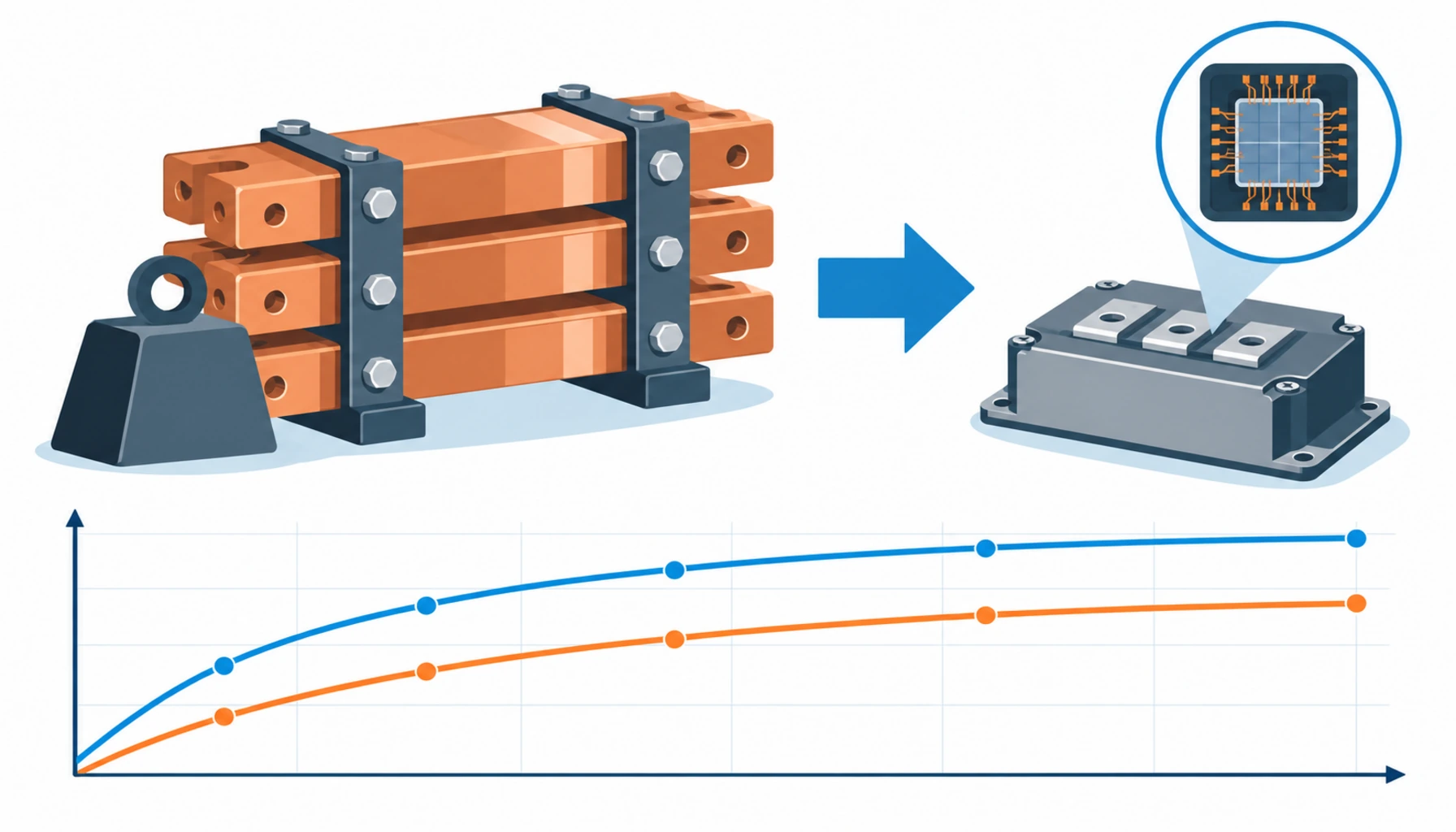
Quick Answer: Rack-level DC-DC conversion exists because copper ran out of room. Moving the step from 800V down to the rack’s internal rail into a rack-side converter shrinks the busbar, but it moves the cost, the heat and the risk onto silicon — and that is a different supply chain with different failure modes and a different way of being specified.
The phrase the industry uses for this shift is silicon replacing copper. It is a useful shorthand because it names the trade exactly: every kilogram of busbar you remove from the rack becomes a semiconductor device that has to be bought, cooled, efficiency-verified and eventually replaced. The procurement consequence is that a line item which used to be a metal purchase is now an electronics purchase, with everything that implies about supply chain, specification and warranty.
Introduction
In a 54V rack the converter that produces the low voltage rail sits inside the server power supply, and the rack-level distribution problem is one of moving a very large current a very short distance. That is why the copper was the limit — at roughly one megawatt, a 54V rail carries close to eighteen and a half thousand amps, which is not a busbar problem that can be solved by buying a bigger busbar.
Raising the distribution voltage fixes the copper problem and creates a conversion problem. Something has to step 800V down to the voltage the silicon in the rack actually wants, and the two candidates are a rack-side power shelf doing the conversion outside the server, or converters distributed inside each server. The first is cleaner and is where the industry is heading; the second avoids a shared failure domain. Either way, the buyer is now purchasing power electronics with a specification that has more in common with a drive than with a cable. The architecture that created this requirement is described in our note on 800V DC data center power.
Four Ways to Get From the Busway to the Rack Rail
The conversion decision cascades through the rack design, the cooling design and the support model. The comparison below sets out what each route asks you to buy, and where it puts the risk.
| Approach | What You Buy | What Must Be Specified | Cost and Supply Position | Main Risk |
|---|---|---|---|---|
| 54V with in-server conversion | PSU modules inside each server, heavy rack busbar | PSU efficiency curve, rack busbar rating for the current | Mature, multi-source, cheapest per unit — but copper and rack volume are the limit | At high density the busbar becomes a bespoke build, not a catalogue item |
| Rack-side power shelf | A shelf of DC-DC converters converting 800V to the rack rail | Input voltage window, efficiency at part load, load sharing, hot-swap rating | Growing supply base, driven by the 800V roadmap vendors | Shared failure domain — one shelf serves the whole rack |
| Distributed converters in-server | A converter module per server, fed from the 800V busway | Isolation, input protection, thermal path inside the chassis | Higher unit count, more complex support model | Per-server design ownership makes standardisation hard |
| Direct 800V to point of load | Converters stepping straight to the board rail | Transient response, decoupling, fault containment | Fewest stages and best efficiency on paper, youngest supply base | Unproven at scale and hard to service in the field |
Why the Efficiency Curve Matters More Than the Peak Number
A converter datasheet leads with a peak efficiency figure, usually measured somewhere near half load and often at a temperature the rack never sees. It is the least useful number on the page for a data center buyer, because a hall does not run at a fixed load. It runs at partial load most of the time and at high load during training runs, and the shape of the efficiency curve between those two points decides the electricity bill and the heat rejection requirement.
Ask for the curve, not the peak. Specifically, efficiency across the load range from roughly twenty to one hundred percent, at the input voltage you will actually run, at the ambient the shelf will see, and with the device configuration that will ship. Two shelves with the same headline number can differ by several percentage points at low load, and at rack scale that difference is a real line in the operating budget.
The input voltage window matters almost as much. An 800V nominal supply with normal regulation and transient behaviour is not a constant 800V, and a converter specified for a narrow window will either derate or trip at the edges of what the distribution system actually delivers. Write the window into the enquiry, and make the vendor confirm the efficiency curve holds across it rather than only at nominal.
Efficiency also has a second-order procurement effect that is easy to miss. Losses are heat, heat has to be removed, and in a liquid-cooled hall the cooling system capacity is bought early and sized to the IT load. A converter that is one percent less efficient at part load changes the heat rejection figures that the cooling package was specified against. Our note on high density rack cabling covers how that interacts with the rack layout.
Wide Bandgap Devices and the Supply Chain Behind Them
The reason rack-level conversion is possible at all at these power densities is the shift to wide bandgap semiconductors — silicon carbide and gallium nitride devices that switch faster, run hotter and waste less energy than silicon equivalents. That is also where a procurement team inherits a supply chain it may not have dealt with before.
Wide bandgap devices have a narrower manufacturing base than conventional silicon power devices and a longer qualification cycle. They also come with a set of specification questions that do not exist in the silicon world: gate drive requirements, switching transient behaviour, and the fact that a faster switching device makes electromagnetic interference a design problem rather than an afterthought. For a buyer, none of this is a reason to avoid the technology. It is a reason to ask where the devices come from and what happens if that source is constrained.
Two practical consequences belong in the purchase order. First, ask for the second-source position on the critical semiconductor content, in the same way you would on any single-sourced component. Second, ask for the compliance evidence for the whole assembly rather than the module, because a converter shelf is an assembly of devices, magnetics and control electronics and it is the assembly that has to meet the emissions and safety requirements in the destination market.
The control side deserves a question too. A rack-side converter reports its own status, and that telemetry is what makes rack power visible to the monitoring system. If the converter’s control interface is proprietary or poorly documented, the hall inherits a monitoring gap exactly where the highest currents are. Our inverters and power conversion range is the conventional reference for how these products are specified and documented, and the questions transfer directly.
What to Freeze Before the Converter Order
Each item below is a place where a converter supplier will apply a default unless the enquiry closes it out.
| Specification Item | What to State | Evidence to Demand | Cost of Leaving It Open |
|---|---|---|---|
| Input voltage window | The full range the distribution system delivers, including transients | Efficiency and operation confirmed across the whole window | Derating or nuisance trips at the edges of normal operation |
| Efficiency across load | The curve from about twenty to one hundred percent load at your ambient | Measured curve at the shipping configuration and input voltage | An electricity and heat rejection bill different from the design case |
| Load sharing and hot swap | Number of modules, sharing accuracy, and removal under load if required | Hot-plug rating at load current and transient limits during a swap | Maintenance access that requires an outage after all |
| Thermal path and cooling | Air or liquid cooling, coolant specification, heat rejection per shelf | Heat rejection figures at the load profile, not at peak efficiency | A shelf that cannot be cooled by the system already bought |
| Semiconductor sourcing | The critical device sources and the second-source position | Named device sources and a qualification plan for the alternate | A supply constraint that stops a whole rack generation |
| Telemetry and control | Protocol, data points exposed, alarm thresholds and integration method | Interface documentation and a point list | A monitoring gap exactly where the currents are highest |
| Emissions and safety compliance | The destination market requirements, applied to the assembly | Certificate for the assembly, not for the constituent modules | Equipment that cannot be signed off in the destination market |
| Service model | Field replaceable units, spares holding, and standing lead times | FRU list and delivery commitments with dates | A rack generation that cannot be repaired at a sensible speed |
When Rack-Level Conversion Is Not the Right Buy
Putting the conversion in a rack-side shelf is the right answer for high-density AI racks with a roadmap toward 800V. It is the wrong answer in three situations.
Moderate density where the copper problem does not exist. Below roughly 100 kW per rack, in-server conversion from a conventional AC supply is cheaper, better supported and available from a very wide supplier base. It also removes an entire rack-level failure domain, which is worth more than the efficiency gain at that density. The conventional topology is described in our note on 415V data center distribution.
Operations without the skills to service power electronics. A rack-side converter shelf is a repairable electronic assembly, not a passive component. It needs spares, firmware management and people who understand the difference between a converter fault and a load fault. A facility structured around swapping cables and breakers is not automatically set up to support it, and the cost of building that capability belongs in the business case rather than in a later surprise.
Racks where a shared conversion shelf is unacceptable. A single shelf serving a whole rack concentrates the failure domain. Applications that cannot tolerate that concentration should either distribute the conversion or keep the conventional arrangement, and the decision is an availability one rather than a cost one. How the redundancy arithmetic works out is covered in our note on N+1 versus 2N UPS redundancy, and it applies unchanged here.
The wider point is that rack-level DC-DC conversion is a purchase of electronics, not of distribution hardware. It should be specified with an efficiency curve, a thermal figure, a semiconductor sourcing answer and a service model — four things that never appear on a busbar datasheet because nobody ever needed them there. Where the boundary between the converter and the distribution unit sits is the subject of our note on rack and floor mounted PDUs.
RFQ Checklist for Rack-Level DC-DC Conversion
Send the load profile and the environment, not just the power rating. Each enquiry should carry:
- Rack power per rack and the load profile over a typical operating day and week
- The input voltage window the distribution system delivers, including transient excursions
- Required output rail voltage and current, with the tolerance the server accepts
- Efficiency curve required across the load range, at the stated input and ambient
- Cooling method, coolant specification if liquid, and maximum permitted heat rejection
- Whether hot swap is required, and the redundancy position during a module removal
- Telemetry protocol and the data points your monitoring system expects
- Critical semiconductor sources and the second-source qualification plan
- Compliance requirements for the destination market, applied to the assembly
- Field replaceable unit list, spares holding and standing lead times with dates
- Warranty terms for the converter shelf, and the treatment of consumable parts
Conclusion
Rack-level DC-DC conversion is where a distribution budget quietly becomes an electronics budget. The copper shrinks, and in its place comes a converter shelf that has to be specified with an efficiency curve across the real load range, a heat rejection figure the cooling system can absorb, a semiconductor sourcing answer, and a service model with spares and standing lead times. Miss any of those and the rack is cheaper to build and more expensive to run.
The buyers who get value from this transition treat the converter as the critical item it is, rather than as a power supply that arrives with the rack. Kexingyu Cable Group (KXYE) supplies the power, control and mineral insulated cable ranges that feed these racks — WDZ-YJY, WDZN-YJY, BTTZ, BBTRZ, NG-A (BTLY), KVV and YJV — together with distribution cabinets, busbar tap-off boxes and medium voltage switchgear, from a single factory group, with copper price linkage available on project-scale orders. Send your rack power profile, voltage window and cooling arrangement and we will size the cable and distribution side of the package; the fastest start is a request for quotation.


