
415V/240V Distribution: Why AI Data Centers Run at Higher Voltage
Quick Answer: Raising distribution voltage cuts current per rack, allowing smaller copper cross-sections and fewer parallel sets — which is why AI-era facilities keep pushing voltage up. Voltage is a lever, and distribution designers have been pulling it for a century: the higher the voltage, the lower the current for the same power, and the less copper needed to carry it. AI rack densities have turned that old lever into a strategic decision. A hall that once distributed 5 kW per row now moves 30 kW per rack, and the difference between running that power at 230 V and at 240 V, or between a 400 V and a 415 V bus, shows up directly in the cable schedule.
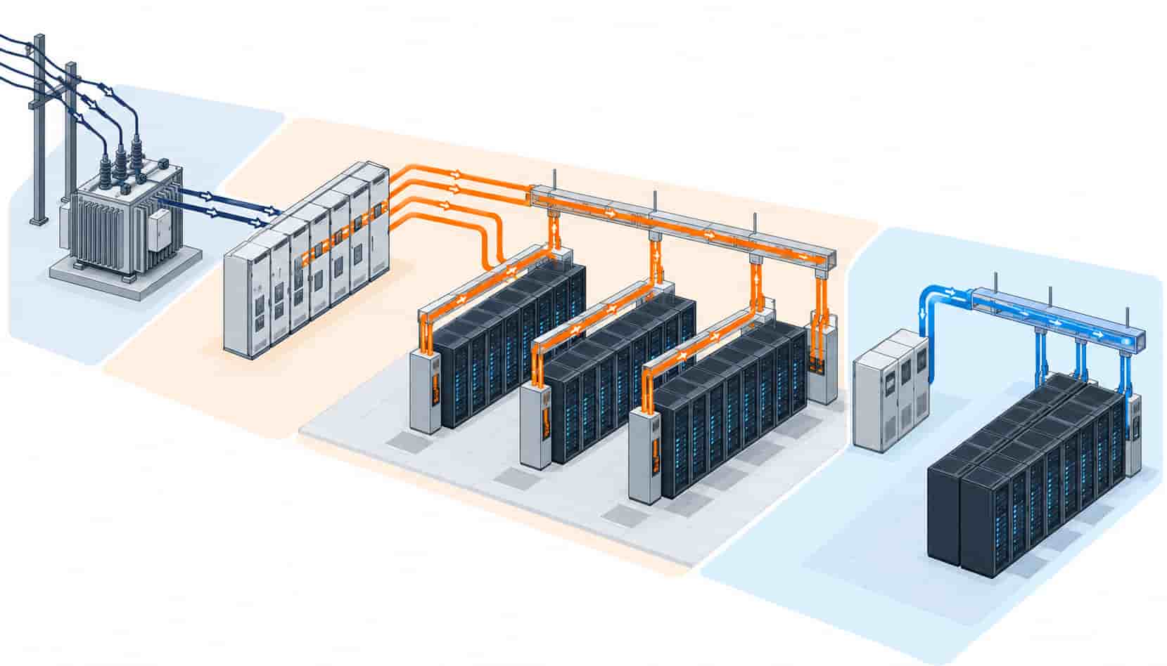
Introduction
Most of the world’s data centers distribute at nominal three-phase 400/230 V (50 Hz markets) or 480/277 V (60 Hz NEC markets), with 415/240 V appearing where the design wants a little more headroom inside the same LV insulation class. The physics is unforgiving and simple: power equals voltage times current times power factor, so every volt of extra distribution voltage buys a proportional reduction in current — and current is what copper cares about. As AI clusters multiply per-rack power, the industry has seized every legitimate volt, and the trend continues upward into rack-level HVDC schemes at 240 V and 336 V DC that modular data center lines now ship as standard options.
This article explains what the voltage choice does to cable selection in practice: how 415/240 V compares with 400/230 V for feeders, why parallel sets shrink as voltage rises, where the transformer tap sits in all of this, and what the cable schedule must state so the factory prices the right insulation class and cross-section. The upstream equipment — the transformers and switchgear that set these voltage levels — is covered system by system in our transformers and substations collection.
The Arithmetic of a Few Extra Volts
For the same 30 kW rack at unity-minus-typical power factor, a 415 V three-phase bus carries about 4% less current than a 400 V bus. That alone is rarely decisive for one rack — but distribution works at every level of the hall, and the percentages compound where it matters most: the row feeder and the switchboard riser. A 1,000 A row bus at 400 V becomes a 960 A bus at 415 V, which can be the difference between a single large cross-section feeder and a parallel set, between a 240 mm² and a 185 mm² conductor, or between one tray position and two.
The savings scale with distance too. Voltage drop is proportional to current times length, so longer routes benefit twice: less current to drop, and less copper to fix the drop. Halls with centralized UPS plant and long LV feeders gain the most, which is one reason high-density designs concentrate distribution at higher voltage before the last transformation to the rack. The cross-section selection method underneath all of this — load current, correction factors, drop check — is walked through in our cable size selection guide.
| Voltage Level | Where It Appears | Cable Effect | Specification Anchor |
|---|---|---|---|
| 400/230 V | Standard LV distribution in 50 Hz markets | Baseline current; larger feeders at high row density | IEC 60502-1, 0.6/1 kV |
| 415/240 V | LV buses chosen for current headroom in AI halls | About 4% less current; smaller cross-sections on long runs | IEC 60502-1, 0.6/1 kV; transformer tap set accordingly |
| 480/277 V | NEC-market distribution in 60 Hz regions | Comparable headroom; product certification differs | UL-listed products per destination market |
| 240 V DC rack bus | HVDC distribution in modular AI facility designs | Dedicated DC-rated cable, polarity marking, different protection | Project DC distribution spec; DC-rated accessories |
| 336 V DC rack bus | Higher-voltage HVDC for dense AI rows | Least current per kW at rack level; least common accessories | Vendor-locked ecosystems; verify cable compatibility |
What the Voltage Choice Means for Cable Procurement
Between 400/230 V and 415/240 V, the insulation class does not change — both live comfortably inside 0.6/1 kV XLPE, the workhorse of LV distribution whose insulation physics are explained in our guide to XLPE cable. What changes is conductor size, and that is a procurement matter: fewer square millimetres per route, fewer parallel sets per feeder, less tray fill. Buyers quoting a hall in 415/240 V should make sure the cable schedule states the distribution voltage explicitly, because a quoting factory that assumes 400 V will size slightly heavy — safe, but not priced sharp.
The more disruptive shift is rack-level DC. Hyperscale operators have long run 240 V DC distributions internally, and 336 V DC has followed as AI densities climb; modular facility products now bundle these HVDC buses as pre-engineered options. For the cable buyer, DC changes three things: accessories must be DC-rated (protection devices, connectors, monitoring), cable polarity and marking conventions apply, and the LV AC cable families — YJV, WDZ-YJY — remain usable for many DC routes as conductors, but the schedule must say so explicitly rather than assume interchangeability.
Where the Transformer Fits In
Distribution voltage is set upstream, at the transformer. The difference between a 400 V and a 415 V secondary is usually a tap position on the same unit, which is why the electrical designer and the transformer supplier need to agree the no-load and loaded voltage profile early — a transformer set on the wrong tap either starves the hall at peak load or pushes light-load voltage above equipment tolerance. Capacity sizing and tap selection interact with every downstream cable decision, which our guide to transformer capacity sizing develops from the load-study side.
Step-down topology matters as well. Whether the hall takes one large step from MV to 415 V or stages through an intermediate level changes both the transformer count and the LV feeder lengths — the cable-heavy part of the installation. The trade-offs between direct and staged transformation are compared in step-up versus step-down transformer selection, and the insulation choice for the transformers themselves (which determines whether they can sit inside the hall, shortening LV runs dramatically) is laid out in oil-immersed versus dry-type transformer comparison.
415/240 V in Practice: What Changes on Site
For the installation crews, a 415/240 V hall looks almost identical to a 400/230 V hall — same trays, same glands, same 0.6/1 kV cable — which is precisely why the change is cheap to make at design stage and expensive to make later. The discipline points are three. First, protection settings and equipment ratings must match the actual bus voltage, not the nominal regional one. Second, single-phase loads at 240 V instead of 230 V are within tolerance for virtually all modern equipment, but the UPS bypass and PDU tap settings must be verified. Third, mixed-voltage documentation: cable schedules, labels and as-builts should carry the true bus voltage so future modifications do not guess.
The cable factory’s role is narrower but real: confirm the insulation class covers the actual maximum continuous voltage with margin, size conductors to the design current at that voltage, and mark drums with the project voltage class so site distribution is unambiguous. Batch test reports then close the loop between what was ordered and what was wound.
| Check Item | What to Confirm | Why It Matters |
|---|---|---|
| Insulation class | 0.6/1 kV XLPE across LV distribution | Covers 415/240 V with standard margin; no exotic product needed |
| Conductor sizing | Based on 415 V design current, not 400 V habit | 4% current reduction sharpens pricing on long, heavy feeders |
| Transformer tap | Agreed no-load and loaded voltage profile with supplier | Wrong tap starves or overvolts the hall at the extremes |
| Protection and PDU settings | Matched to actual bus voltage | Nominal-regional settings drift out of tolerance |
| DC routes (if HVDC) | DC-rated accessories and explicit polarity marking | AC assumptions do not transfer silently to DC buses |
| Drum marking | Project voltage class on every drum label | Prevents mixed-voltage confusion across phased deliveries |
When Higher Voltage Is Not the Answer
The voltage lever has limits. Pushing LV buses higher than the 415-480 V band buys nothing, because the next meaningful step — medium voltage distribution into the hall — changes the entire product class, protection philosophy and certification scope, and only pays in very large campuses where the LV runs would otherwise be extreme. For most halls, the sensible sequence is: agree the transformer tap and bus voltage early, size conductors to the real design current, and reserve the voltage conversation for rack-level DC where the ecosystem (and its pre-engineered facility products) has already done the heavy lifting.
There is also a people limit. Maintenance crews, spare-part inventories and site habits are built around the hall’s nominal voltage; a bespoke scheme that saves 2% of copper but confuses every subsequent intervention has traded recurring operational risk for a one-off material saving. Voltage decisions deserve the same lifecycle accounting as every other specification choice.
RFQ Checklist: Ordering Cable for a 415/240 V Hall
Make the voltage explicit and the offer sharp:
- Single-line diagram showing the distribution voltage at each bus level
- Design currents calculated at 415/240 V, with correction factors applied per route
- Transformer secondary voltage and tap arrangement confirmed with the supplier
- Cross-section preferences or the load schedule for the factory to size against
- Any DC rack-bus routes identified separately with DC-rated accessory requirements
- LSZH sheath and flame spread class for technical-room routes
- Parallel set requirements: identical lengths, phase arrangement, containment type
- Drum length plan matched to routing, with voltage class marked on labels
- Batch test reports including conductor resistance evidence
- Copper price linkage terms for the project delivery window
That final line compounds across a hall: a 415 V design already trimmed the copper, and a copper price linkage keeps the trimmed budget intact between order and delivery, which on a multi-tonne order is worth more than any per-metre discount.
Conclusion
The move to 415/240 V distribution in AI-era halls is not exotic engineering; it is old arithmetic applied to new densities. Higher bus voltage trims current, current trims copper, and the trim arrives at exactly the feeder levels where high-density rows hurt. The cable scope barely changes in product class — 0.6/1 kV XLPE still does the work — but it changes meaningfully in cross-section, and the schedule that says so explicitly is the one that prices correctly.
If you are fixing the distribution voltage for a high-density hall, bring the single-line and load schedule to Kexingyu Cable Group (KXYE). We size the LV scope at your actual bus voltage, mark and pack to the project schedule, and hold the copper basis with price linkage from order to delivery — one factory group for the feeders, the flexible rack connections and the fire-rated risers that complete the chain.


