
Step-Up vs Step-Down Transformers Explained
A practical guide to voltage ratios, current, losses, applications, protection, and the details buyers must specify before ordering
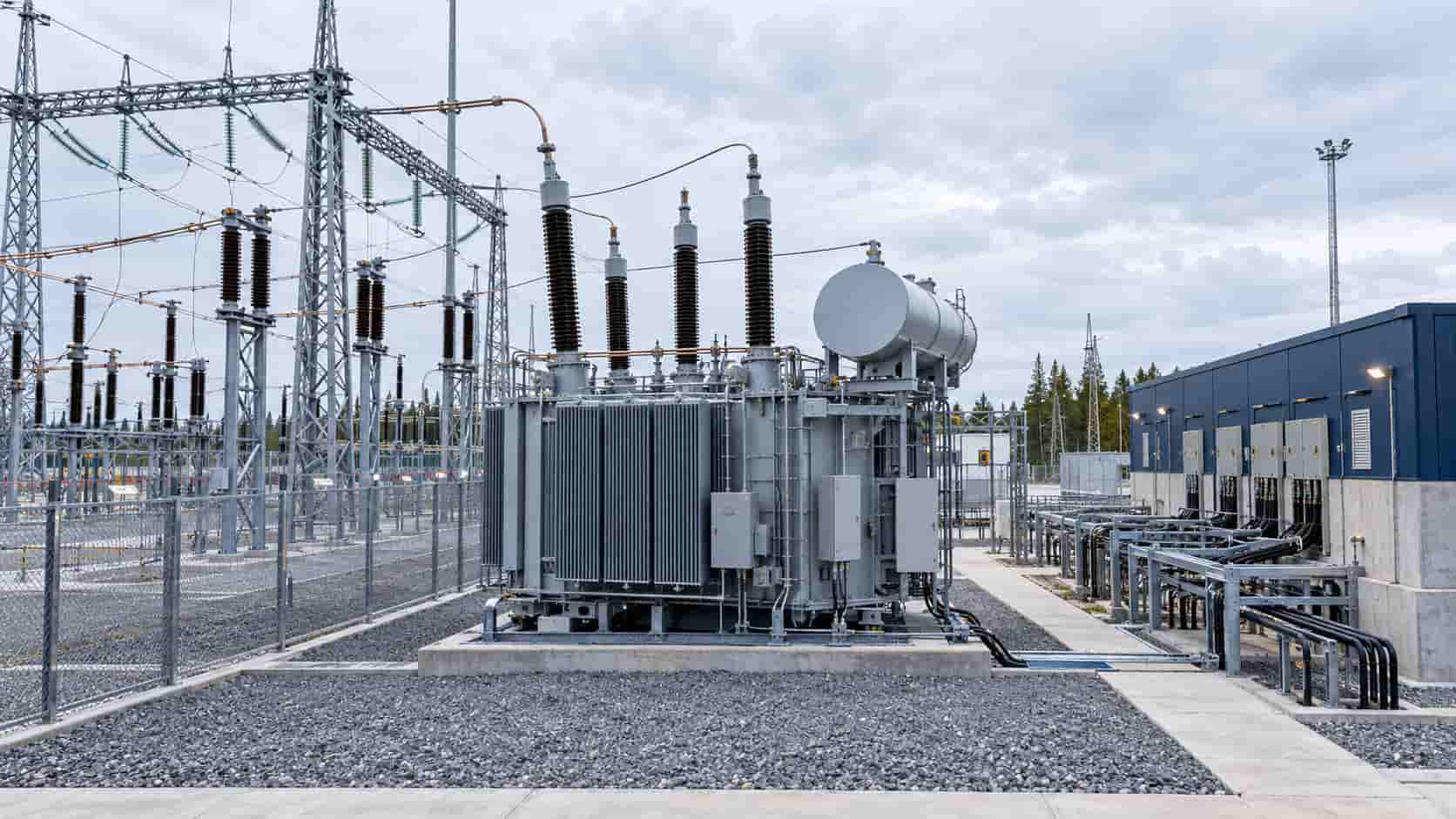
A step-up vs step-down transformer comparison sounds simple: one raises voltage and the other lowers it. For a real project, however, the direction label is only the beginning. Buyers also need to understand current, winding ratio, kVA, losses, vector group, grounding, insulation, protection, taps, load behavior and whether the intended source side matches the transformer’s design.
The distinction matters across the power system. Generator and renewable plants use step-up transformers to connect lower-voltage generation to a higher-voltage network. Utilities and industrial facilities use step-down transformers to reduce transmission or distribution voltage to levels suitable for local distribution and equipment.
Step-Up vs Step-Down Transformer: The Core Difference
A transformer is described from the intended direction of power flow. If the energized source-side voltage is lower than the receiving-side voltage, it is operating as a step-up transformer. If the energized source-side voltage is higher, it is operating as a step-down transformer.
For an ideal transformer, the voltage ratio follows the effective turns ratio: Vs/Vp = Ns/Np. The current ratio moves in the opposite direction: Is/Ip = Np/Ns. In practical terms, raising voltage reduces current for approximately the same transferred kVA, while lowering voltage increases current. Real transformers also have copper, core and stray losses, so output power is always below input power.
The U.S. Department of Energy explains that distribution transformers step voltage down for consumer use, while renewable generation requires step-up units with similar distribution-transformer characteristics. KEXINGYU transformer and substation solutions cover voltage transformation for utility, industrial and special-duty applications, subject to project-specific engineering review.
How a Transformer Changes Voltage and Current
The turns ratio sets the nominal voltage ratio
Alternating current in the energized winding produces changing magnetic flux in the core. That flux induces voltage in the other winding. A winding with more effective turns develops a higher voltage; a winding with fewer turns develops a lower voltage. The relationship is approximate at the terminals because winding impedance and load current cause voltage drop.
Higher voltage means lower current for similar kVA
Ignoring losses, apparent power is approximately conserved. For single-phase systems, S = V x I. For balanced three-phase systems using line values, S = square root of 3 x Vline x Iline. A step-up transformer therefore reduces current on the higher-voltage side, which supports lower conductor losses and practical long-distance transmission. A step-down transformer produces higher current on the low-voltage side, so its terminals, conductors, busbars and protection may need substantial current capacity.
A transformer does not create power or change frequency
Voltage can increase while current decreases, but the transformer does not multiply energy. Nameplate kVA, temperature limits, losses and cooling still govern loading. A conventional 50/60 Hz transformer also does not convert frequency. Applying the wrong voltage-to-frequency ratio can drive excessive core flux, noise, heating and damage.
Step-Up Transformer: Where and Why It Is Used
A generator step-up transformer raises generator-terminal voltage to a transmission or sub-transmission level. Hitachi Energy describes the GSU as the critical link between a power station and the transmission network. Solar and wind projects similarly use step-up transformers between inverter or turbine collection voltage and the grid interconnection voltage.
Industrial applications also use step-up transformers when locally available voltage is below an imported machine’s required voltage or when a test system needs a higher operating level. Those cases require more than selecting a ratio: the designer must confirm isolation, grounding, fault current, inrush, duty cycle and equipment compatibility.
Key step-up design concerns
The higher-voltage winding needs suitable insulation coordination, clearances, bushings and impulse withstand. Generator and inverter-fed applications may introduce harmonics, unusual load cycles, rapid voltage changes or special protection requirements. The engineer must define the source characteristics, grid code, expected overvoltage, short-circuit duty, neutral treatment and surge protection.
Step-Down Transformer: Where and Why It Is Used
A step-down transformer reduces network voltage to a usable distribution or equipment voltage. Common examples include substation transformers feeding an industrial medium-voltage system, distribution transformers supplying commercial or residential loads, and facility transformers converting medium voltage to 400/230 V, 480/277 V or another local system voltage.
Voltage-matching units may also supply imported machinery. For example, the QSG three-phase dry-type isolation transformer can be configured to step an incoming three-phase voltage down or up while providing galvanic isolation. The exact application still determines capacity, winding arrangement, enclosure and protection.
Key step-down design concerns
The low-voltage side may carry very high current. Buyers must check terminal size, cable quantity, busbar connection, neutral rating, enclosure heat dissipation and downstream short-circuit protection. Motor starting, UPS rectifiers, EV chargers, variable-frequency drives and other nonlinear loads can influence voltage dip, harmonic heating and neutral current.
Step-Up vs Step-Down Transformer Comparison
| Comparison Point | Step-Up Transformer | Step-Down Transformer |
|---|---|---|
| Main function | Raises voltage from the source side to the receiving side | Reduces voltage from the source side to the load side |
| Typical grid position | Generator, solar or wind collection system to transmission/distribution grid | Transmission or distribution network to facility, equipment or final-use voltage |
| Winding relationship | Receiving-side winding has more effective turns than source-side winding | Receiving-side winding has fewer effective turns than source-side winding |
| Current relationship | Receiving-side current is lower for approximately the same transferred kVA | Receiving-side current is higher for approximately the same transferred kVA |
| Common design emphasis | High-voltage insulation, surge duty, generator or inverter interface, grid-side protection | Low-voltage current capability, terminals or busbars, neutral/grounding, load starting and fault coordination |
| Typical examples | Generator step-up unit, renewable plant step-up transformer, substation intertie | Utility distribution transformer, facility service transformer, machine voltage-matching transformer |
The comparison table describes the intended operating direction, not two completely different electromagnetic machines. Both types can be single-phase or three-phase, liquid-immersed or dry-type, and built with two separate windings or an autotransformer arrangement. Their design details change because the source, receiving system and duty are different.
Can One Transformer Work in Both Directions?
Power flow through many conventional two-winding transformers is physically reversible. A unit labeled 11 kV/0.4 kV could, in principle, be energized from the 0.4 kV winding and deliver voltage on the 11 kV winding. That observation is not a blanket approval for reverse operation.
The available taps may be placed on the winding originally intended as the supply side. Voltage regulation may not produce the required output when the direction changes. Grounding and neutral arrangements can become unsuitable. Protection, surge arresters, metering and inrush assumptions may be wrong. An auxiliary power or control system may also expect a particular source side.
Reverse energization should therefore be confirmed by the manufacturer or a qualified transformer engineer. The review should cover winding ratings, taps, insulation coordination, vector group, grounding, zero-sequence behavior, inrush, fault duty, cooling, accessories and nameplate marking.
Isolation Transformer vs Autotransformer
Step-up and step-down describe voltage direction. Isolation transformer and autotransformer describe winding construction. A two-winding isolation transformer has separate primary and secondary windings coupled magnetically, which can provide galvanic separation when applied correctly. An autotransformer shares part of one winding between input and output, making it smaller and often more efficient for modest ratios but without galvanic isolation.
Do not assume a voltage converter automatically isolates the load. If isolation, separately derived system grounding, common-mode noise control or fault separation is required, state it explicitly in the specification.
Why Vector Group, Grounding, and Phase Shift Matter
For three-phase transformers, the voltage ratio alone does not define system compatibility. Wye, delta and zigzag connections affect neutral availability, grounding, zero-sequence current, harmonic behavior and protection. The vector group also defines the phase displacement between windings.
A replacement transformer with the correct kVA and voltages but the wrong vector group may not operate in parallel with existing units and may create serious protection or circulating-current problems. Buyers should specify the required vector group, neutral insulation and loading, grounding method, phase sequence and any parallel-operation requirement.
Losses, Efficiency, and Voltage Regulation
No-load and load losses
Core loss exists whenever the transformer is energized and is mainly influenced by voltage, frequency, core design and material. Load loss rises with current and includes winding resistance and stray effects. A transformer serving a continuously loaded industrial process may justify a different loss evaluation from one used only for standby or intermittent duty.
Impedance and regulation
Percentage impedance affects voltage drop and available short-circuit current. Lower impedance can improve regulation but increases prospective fault current; higher impedance limits fault current but can worsen voltage dip during motor starting or step-load changes. The correct value is a system coordination decision, not simply the lowest number available.
Tap changers adjust voltage within a defined range
Off-circuit taps require the transformer to be de-energized before adjustment. On-load tap changers can regulate voltage while energized within their designed range. Taps compensate for system voltage variation; they do not turn an unsuitable transformer into a universal voltage converter.
Protection and Testing Requirements
Protection depends on transformer size, construction and system importance. Typical elements may include overcurrent and earth-fault protection, differential protection, restricted earth fault, temperature devices, pressure or gas protection for liquid-filled units, surge arresters and low-voltage breaker coordination. Protection settings must account for magnetizing inrush without leaving internal faults inadequately protected.
Power-transformer specifications commonly reference the IEC 60076 series or applicable IEEE/ANSI requirements, together with local regulations and utility rules. Routine, type and special tests should be listed explicitly rather than requested as an undefined ‘full test.
How to Specify the Right Transformer
1. Define both systems, not only two voltage numbers
State source and receiving voltages, voltage tolerances, phase, frequency, grounding, neutral requirements, fault levels and whether the figures are line-to-line or line-to-neutral. Identify the intended energized side and normal power-flow direction.
2. Size kVA from the actual load profile
Include continuous demand, diversity, future growth, motor starting, cyclic loads, nonlinear loads, ambient conditions and required redundancy. Do not size solely by adding connected equipment nameplates or by converting kVA to kW without power factor and efficiency assumptions.
3. Specify electrical performance
Define vector group, impedance, tap range and step, insulation level, temperature rise, cooling, loss or efficiency requirements, sound limits, harmonic duty and permissible voltage regulation. State parallel-operation requirements if applicable.
4. Define the installation environment
Indoor or outdoor location, altitude, ambient temperature, humidity, pollution, salt, dust, seismic duty, enclosure rating, fire constraints and fluid requirements affect design. Dry-type and liquid-immersed options should be evaluated against the actual site rather than selected by a generic rule.
5. Confirm terminals, accessories, protection, and tests
Provide cable or busbar interfaces, terminal orientation, neutral connection, monitoring, fans, marshalling box, protection devices, communications, test standards, witness requirements, drawings and documentation. Coordinate both sides with switchgear, cables and protective-device ratings.
Common Selection Mistakes
Assuming voltage ratio is enough. Two units with identical voltages can differ in vector group, impedance, insulation, taps, losses, thermal design, terminals and grounding behavior.
Calling any voltage-changing unit an isolation transformer. Autotransformers and two-winding transformers have different fault and grounding implications.
Ignoring the higher current side. Step-down low-voltage terminals may require multiple large cables or busduct, while a step-up design may place more demanding insulation and surge requirements on the receiving side.
Reversing a transformer without engineering approval. Physical reversibility does not guarantee suitable taps, regulation, protection, grounding or accessory operation.
Using a 50 Hz unit at 60 Hz or a 60 Hz unit at 50 Hz without checking volts per hertz. Frequency and voltage must remain within the manufacturer’s approved limits.
Conclusion
The essential step-up vs step-down transformer difference is the intended voltage direction: step-up raises voltage and lowers current, while step-down lowers voltage and raises current for approximately the same transferred kVA. That simple definition must be combined with system engineering.
A reliable purchase specification should define kVA, source and receiving systems, frequency, vector group, grounding, impedance, taps, insulation, cooling, losses, load behavior, protection, terminals and tests. KEXINGYU E-POWER GROUP can review transformer and substation requirements for utility, industrial and voltage-matching projects. Final configuration should be confirmed against project drawings, applicable standards and the actual network study.
Recent Posts
Energy Storage for Data Centers: A Growing Backup Power Option
Energy Storage for Data Centers: A Growing Backup Power Option Batteries have always backed up data centers in the form of UPS strings. Grid-scale BESS
Thermal Runaway in Lithium Batteries: What BESS Buyers Should Understand
Thermal Runaway in Lithium Batteries: What BESS Buyers Should Understand How thermal runaway starts, how it propagates, and which evidence buyers should require before approving
Switchgear Lead Times in 2026: A Buyer’s Planning Guide
Switchgear Lead Times in 2026: A Buyer’s Planning Guide Realistic timelines vary significantly by voltage class and type — here’s how to plan procurement without