
A/B Redundant Feeds: Cable Redundancy Design for Data Centers
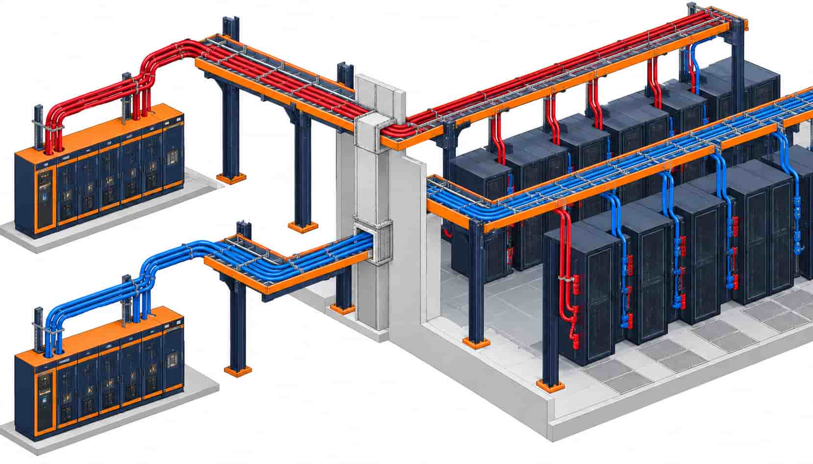
Quick Answer: A/B redundancy is only as real as the physical separation of the two cable routes — dual paths from different switchboards that never share a fire zone or failure point. Every data center single-line diagram shows two feeds to every critical load. The diagram is the easy part. What actually protects the load is the physical truth that path A and path B never touch: different switchboards, different risers, different trays, different rooms where possible. The moment two "redundant" cables share a tray, a gland plate or a fire compartment, the redundancy exists on paper only — and audits keep finding exactly that gap.
Introduction
Redundancy tiers — N+1 at the equipment level, 2N at the system level — are usually discussed as UPS and switchgear questions. Cable is where the scheme becomes physically real, because conductors are the only part of the chain that stretches continuously between rooms. A 2N electrical design served by cables that converge in one tray has a hidden common failure point that no amount of UPS capacity repairs. This article works through cable redundancy in practice: what A/B means at each level of the power chain, how dual-corded racks change the last metres, the routing rules that keep paths independent, and how to document the separation so that concurrent maintainability is provable, not aspirational.
The system-level redundancy logic — what N+1 and 2N mean for the UPS plant that feeds path A and path B — is developed in our comparison of N+1 versus 2N UPS redundancy, and the transfer technology that often sits between the two feeds is covered in ATS versus STS selection. Here we stay with the copper: what the feeds demand of the cable schedule itself. The equipment rooms those feeds originate from are treated system by system in our data center power collection.
What A/B Means at Each Level of the Power Chain
Redundancy has a different physical shape at every level. From the utility intake and generator plant, A and B are separate MV feeders to separate transformers and separate LV switchboards. Below the switchboards, path A and path B run as independent LV feeders to independent distribution — no shared breakers, no shared bus. At the row, dual busways or duplicated PDU feeds deliver one A circuit and one B circuit to every rack, where dual-corded servers draw from both simultaneously and either cord alone can carry the full load.
The cable implication is that every route is duplicated end to end, and the duplicated routes must fail independently. Independent failure is a routing property, not an electrical one: two cables can be electrically separate while sharing every physical vulnerability — the same tray that collapses, the same riser that floods, the same contractor who cuts the wrong conduit. The design question is therefore spatial first and electrical second.
| Level | Redundant Element | Physical Separation Required | Common Failure to Design Out |
|---|---|---|---|
| MV intake | Two utility supplies plus generator plant | Separate cable entries and routes into the campus | Shared trench or single entry room |
| Transformer to LV board | Independent transformer-board pairs for A and B | Separate rooms or fire-rated divisions | Shared transformer room without compartmentation |
| LV board to row | A and B LV feeders | Different tray routes; no shared tray section | Converging trays above a single corridor |
| Row to rack | Dual busway or duplicated PDU feeds | A and B tap-offs on opposite rack sides | Both cords dressed into one flexible bundle |
| Rack internals | Dual-corded PSUs on A and B | Each cord alone sized for full rack load | Cords bundled so one snag takes both |
Routing Rules That Keep Paths Independent
The working rule in mature specifications is simple: no shared tray, riser, room or fire zone between A and B anywhere in the critical path. In practice that means mirrored routes — path A runs on the east riser while path B runs west; inside the hall, A trays serve rack rows from one aisle end and B from the other. Crossings are inevitable, but a crossing is a point, not a shared route: the design keeps the shared length as short as possible and, where the code requires it, protects one path through the crossing zone with fire-rated construction so a fire that consumes one path cannot reach the other.
Fire performance earns its place here precisely because of redundancy. A route that passes through a compartment boundary may need mineral insulated cable — rigid BTTZ or flexible BBTRZ / NG-A (BTLY) — so the surviving path keeps its rating even while the incident evolves. The distinction between flame spread and fire survival, and why redundant paths are the strongest argument for the latter, is laid out in our LSZH versus fire retardant comparison.
Dual-Corded Racks: The Last Metres Decide
The rack is where redundancy becomes visible to the IT load. Dual-corded servers expect one A cord and one B cord, each fed from its independent path, each capable of carrying the full rack alone. The cabling discipline is unglamorous but decisive: A and B cords leave the rack on opposite sides, dress into separate bundles, and never share a cable manager section that a single mishap could crush. Installations that bundle both cords neatly into one flexible sleeve have converted 2N into N at the last half-metre.
Balancing matters too. Both paths carry the load simultaneously in a dual-corded design, so each conductor is sized for the full rack current, not half of it — the common sizing error in 2N racks. On the A and B PDU inputs, flexible Class 5 conductors with proper strain relief keep terminations sound through the rework that dense racks always see; the sizing method at these levels is the same corrected-ampacity discipline detailed in our cable size selection guide.
Documenting Separation So Audits Pass
Concurrent maintainability claims are tested during commissioning and re-tested at every audit, and the test is documentary as much as physical: can the as-built drawings show that path A can be isolated, de-energized and worked on while path B carries the load? That requires the cable schedule to label every critical-route cable with its path (A or B), its source switchboard and its tray route identifier — three fields that turn a pile of drums into a provable redundant design. Color coding by path, consistent drum labeling and route IDs on trays complete the system.
The factory’s role is to support that discipline: cable delivered with path-identifiable sheath colors or printed markings, drum labels carrying project route IDs, and batch documentation keyed to the schedule so each path’s test records stand alone. Where the two paths order different route lengths on different delivery dates, a supplier with copper price linkage holds the commercial basis stable across both deliveries, so path B does not become the budget’s casualty.
| Check Item | Requirement | Why It Matters |
|---|---|---|
| Route independence | No shared tray, riser, room or fire zone between A and B | Shared sections convert 2N into N silently |
| Crossing treatment | Minimal shared length; fire-rated protection where codes require | A fire on one path must not reach the other |
| Per-path sizing | Each path sized for full load, not load sharing | Dual-corded racks load both paths simultaneously |
| Rack dressing | A and B cords on opposite sides, separate bundles | One snagged bundle defeats rack-level redundancy |
| Schedule fields | Path ID, source board and route ID on every cable line | Makes concurrent maintainability provable at audit |
| Delivery alignment | Path-identifiable colors and route IDs on drum labels | Prevents A/B mix-ups across phased site deliveries |
When A/B Everywhere Is Not the Answer
Full 2N doubles the copper, and not every facility needs it everywhere. The sensible pattern applies full A/B redundancy to the critical IT load and tapered redundancy elsewhere: life-safety and mechanical loads often follow N+1 arrangements with different failure consequences, and office or support spaces rarely justify duplicated feeders. Blanket 2N applied without a load classification exercise spends the redundancy budget where failure costs the least.
There is also a false-economy trap in the other direction: retrofitting a second path through whatever space remains. A path B squeezed into path A’s tray, riser or fire zone provides documentation redundancy rather than physical redundancy — and it fails the audit exactly when the audit matters. If the route study cannot find genuine separation, the honest answers are protected routing, fire-rated construction on the crossing, or accepting and documenting a lower availability class for that load.
RFQ Checklist: Ordering Cable for A/B Redundant Designs
The RFQ should carry the redundancy context so the factory can support the discipline:
- Single-line diagrams for path A and path B, each marked with source switchboards
- Cable schedule with path ID, route ID and routed length for every line
- Per-route design currents sized for full load on each path
- Routing description per route (tray, duct, riser) with shared-crossing sections flagged
- Fire performance requirement for compartment-crossing or protected sections
- Path-identifiable sheath colors or printed marking requirements
- Drum labeling with project route IDs, matched to pulling plans
- Class 5 flexible stranding for PDU and rack-level connections
- Batch test reports filed per path so each route’s records stand alone
- Copper price linkage covering both paths’ delivery windows
Two deliveries, one metal basis: the price linkage line matters twice in 2N projects because path B routinely orders months after path A, and a supplier who holds the copper basis across both windows keeps the redundancy plan from becoming a cost variance.
Conclusion
A/B redundancy is a routing discipline expressed in copper. The electrical topology is settled on the single-line diagram; what makes it real is mirrored physical routes, per-path sizing to full load, disciplined rack dressing and a cable schedule that documents every separation claim. Facilities that treat the cable layer as part of the redundancy design pass their audits; facilities that treat it as commodity conduit discover their N is really N.
Kexingyu Cable Group (KXYE) supplies both paths from one factory group — LV distribution feeders, flexible rack connections, fire-rated mineral insulated sections for protected crossings — with path-identifiable marking, route-ID drum labels and batch documentation keyed to your cable schedule. Send the A/B single-lines and routed lengths, and we will return a sized offer with copper price linkage across both delivery windows.


