
Procuring Data Center Riser Cable: Support, Weight and Fire Stop in the Shaft
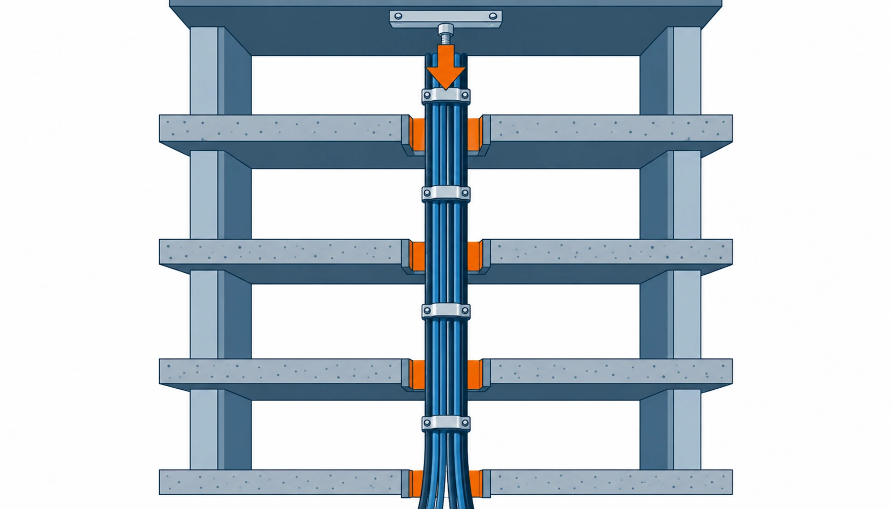
Quick Answer: A horizontal run carries cable across a span; a vertical run hangs it. That single difference turns three things into purchasing decisions that cannot be deferred: the support spacing that carries the weight, the derating that follows from grouping in a shaft, and the fire stop detail at every floor penetration. Buy the cable before those three are settled and you will either install it outside its rating or discover that the seal system has never been tested with the cable you chose. Both are expensive in different ways, and both are decided before the order, not after.
The shaft is usually the last route anyone designs properly and the first one that becomes impossible to change. It passes through every floor, it is shared with whatever else the building needs to move vertically, and the fire stopping at each slab is inspected by someone who is not part of the electrical package. Treating the riser as a cable delivery route rather than as a small structural and fire engineering project is the most common reason that a vertical installation costs more than the horizontal work it connects to.
Introduction
Ask three people on a data center project how much a riser cable weighs and you will get three answers. The cable datasheet quotes mass per metre. The installer quotes a number per cleat. The structural engineer quotes a load at each floor level. All three are needed, and the purchase order usually contains none of them. The consequence appears late: cleats are fixed at whatever spacing the installer habitually uses, the cable settles, and the termination at the bottom of the run takes a load it was never designed to carry.
The second gap is fire stopping. Every floor a riser passes through is a compartment boundary, and each penetration needs a seal that has been tested in the configuration actually being installed. A seal system is approved as a combination of the penetrating item, the substrate and the seal material. Change the cable type, the number of cables, or the tray that carries them, and the approval does not automatically follow. That is why the riser cable and the fire stop system have to be bought as one decision, and why our note on firestop cable penetration systems sets out the interface from the other side.
What the Vertical Geometry Changes
Three effects distinguish a riser from a horizontal run, and each one has a price attached.
Weight becomes a tensile load, not just a bearing load. In a horizontal run the tray carries the cable. In a vertical run the cable carries itself, and every metre adds to the load on the topmost support and on the conductor. A 30 metre riser of large power cable is a substantial hanging mass, and the first cleat below the top termination sees all of it. That is the reason vertical installations often move to steel wire armoured or steel tape armoured constructions: the armour takes the vertical load so the conductor does not. Where armoured cable is not used, the design needs a support wire or a clamped support system that transfers load to the structure at short intervals.
Derating is driven by grouping and by airflow, in opposite directions. A shaft concentrates cables into a small cross-section, which pushes grouping derating factors towards their harsher end. A shaft is also a chimney, which usually gives better airflow than a congested horizontal tray. Which effect wins depends on the shaft construction, whether it is ventilated, and how the cables are arranged against each other. The practical point for a buyer is that the derating basis should be stated in the enquiry along with the arrangement drawing, because the same cable can be compliant or non-compliant depending on how it is bundled in the shaft.
Fire performance stops being theoretical. A vertical route is a path for flame and smoke between floors, and the point of the cable’s fire performance is to slow that path. Because the consequence is compartmentation, the cable’s flame propagation and smoke performance is not a preference on a riser; it is part of whether the building passes inspection. Buying on price alone here shifts cost into the fire stopping and inspection stages, where it is harder to absorb.
The Decision Table: Vertical Route Options Compared
The table compares the ways a vertical route can be built, in the form a buyer can price. The last two columns are the ones that decide the budget: what it costs to install and how it fails when the underlying assumption is wrong.
| Method | What to Declare | Evidence to Demand | Installation and Lead Time Shape | Failure Mode If Chosen Wrong |
|---|---|---|---|---|
| Steel wire armoured cable, clamped | Armour type, total mass per metre, cleat spacing and the load at the top support | Mass per metre on the datasheet, armour cross-section, cleat load rating | Standard cable cycle, 4 to 8 weeks; install time driven by cleat count | Cleats spaced for habit rather than load, and the top termination carries the hang |
| Unarmoured cable on a support wire | The support wire size, its termination method, and who supplies and tests it | Wire and termination load rating, continuity and mechanical test record | Cheaper cable, more site labour and a second item to procure | The support wire becomes the single point of failure and is rarely inspected after installation |
| Ladder tray in the shaft | Bracket spacing per floor, tray load class and the vertical fixing detail | Bracket load test evidence and the fixing schedule to the structure | Fast to install, needs coordination with the fire stop at every slab | Brackets fixed to a non-structural element and the tray settles over the first year |
| Vertical busway riser | Short circuit rating, floor-to-floor dimensions and the fire stop interface at each slab | Type test report, floor interface drawings, tap-off availability | Longest cycle of the options; floor interfaces must be settled before manufacture | Interface dimensions agreed late, and the riser becomes the critical path item |
| Prefabricated riser sections | Floor-to-floor dimensions, termination type and the tolerance you will accept | Factory test record per section, dimensional report, packing and lifting plan | Highest unit cost, lowest site time; every dimension must be confirmed before release | A single floor dimension out of tolerance wastes a whole section and its lead time |
Setting Support Spacing Without Guessing
Support spacing on a vertical run is often set by what the installer has on the van. It should be set by two limits, and both come from documents the buyer can demand.
The first is the cable’s own vertical load capacity. Manufacturers state a maximum vertical span or a maximum tensile load for their constructions, and where the armour is the load path, the armour cross-section is the relevant number. The second is the structure: a cleat transfers load into a slab or a steel member, and the fixing detail has to be capable of taking the cumulative weight of everything above it. The two limits are usually far apart, which is exactly why the assumption stays hidden until something moves.
A useful discipline at enquiry stage is to ask for a simple schedule: cable type, mass per metre, run height, cumulative load at the top support, cleat type and spacing. It is one page, it takes the supplier an hour, and it converts a site argument into a document. Where the schedule shows that the top support load exceeds what the structure comfortably takes, the answer is usually a shorter maximum span or a change of construction, and both are far cheaper to decide before the order than after the cable is on site.
The Fire Stop Detail Decides Which Cable You Can Buy
Fire stopping is where the riser package most often splits into two contracts that do not talk to each other. The cable is bought by the electrical package and the seal is bought by the building package, and the approval that matters covers a specific combination of both.
Three practical consequences follow for whoever is placing the orders.
Confirm the tested combination, not the product. A fire stop system is approved for a defined set of penetrating items at a defined maximum fill. If your riser carries a different cable type, a different size range, or more cables than the tested configuration allows, the approval does not apply, whatever the certificate says at the top. Ask for the tested configuration and compare it to your riser schedule, item by item. The comparison takes minutes and it is the difference between a compliant penetration and a rework order across every floor.
Expect the seal to be inspected, and staff the inspection. Compartment boundaries are inspected by a party outside the electrical scope, usually against photographic records taken during the works. That means the installation sequence matters: if the seal is closed before the cables are labelled and photographed, the evidence is lost and the inspection becomes a visual guess. Our note on cable labeling and documentation for data center handover covers what the record needs to contain.
Buy the fire performance of the cable for the route, not for the room. Where the shaft is the escape path for smoke, the cable’s flame propagation behaviour is the specification item that matters, and it costs more than the equivalent non-fire-rated construction. Deciding to save that step is a decision that lands on the fire stopping, on the inspection, and potentially on the buildings insurance file, which is a poor trade for a cable price difference. The relevant constructions are in our range of fire resistant cable.
What to Freeze Before Releasing the Riser Package
The items below are the ones that turn a vertical installation from an open engineering question into a purchase with a known outcome.
| Item | What to State | Evidence to Attach | Cost of Leaving It Open |
|---|---|---|---|
| Vertical load path | Whether the armour, a support wire or the cleats carry the hang, and the maximum load at the top support | Mass per metre, armour section, cleat load rating, cumulative load schedule | Terminations carrying cable weight, and a defect that surfaces after the first year |
| Cleat type and spacing | Cleat model, spacing in metres, and the torque method for the fixing | Cleat load rating and the fixing detail to structure | Site-chosen spacing, uneven load sharing, and cable slip in the shaft |
| Derating basis | The shaft arrangement the derating factor assumes: layers, spacing, ventilation | Derating calculation referencing the arrangement drawing | Cable operating above its rating in a congested shaft, invisible until the load rises |
| Fire performance class | The flame propagation and smoke requirement that applies to the vertical route | Test evidence for the construction supplied, not a family certificate | Rejection at inspection, or acceptance with a compensating measure that costs more |
| Tested fire stop combination | The exact penetrating items, maximum fill and substrate the seal is approved for | Approval document showing the tested configuration | Every floor penetration reworked, or a seal that is compliant on paper only |
| Floor-to-floor dimensions | Confirmed dimensions per floor with the tolerance you will accept | Surveyed dimensions, signed off before manufacture | Prefabricated sections that do not fit, and their lead time lost |
| Access and lifting plan | How cable is delivered to the top, and the staging floors available | Method statement agreed with the building contractor | Site labour standing while the shaft access is negotiated |
| As-built record | Per-floor penetration photographs, cable schedule and seal documentation in editable form | Deliverable list written into the purchase order | The next phase designed from an incomplete record, and no evidence for the inspection |
When a Riser Is Not the Answer
Vertical distribution is the default in a multi-storey facility, and there are cases where buying it is the wrong call.
Single-storey or low-rise halls. If the building has one or two floors, horizontal distribution from a central plant room usually beats a shaft, because the shaft brings a compartmentation problem and a load path problem and saves almost no cable. Prefabricated and containerised designs often have no vertical route at all, which is one of their quieter advantages.
Shafts shared with other services that cannot be coordinated. Where the route is contested and the programme cannot guarantee the sequence, the better purchase may be a heavier cable with an external armour and an independently braced support system, so the electrical work does not depend on other trades clearing the shaft first.
Retrofits into existing shafts. An existing building rarely offers the slab details the seal system wants, and the derating basis for a shaft that was never designed for cable is unknown. Here the honest answer is often more cable runs at lower fill, which costs copper but avoids a fire engineering exercise the project cannot complete. The trade-off in a live building is set out in our note on high density rack cabling.
Where the equipment supply is the real constraint. Vertical busway brings the same supply position as the rest of the switchgear package, and a riser is not worth waiting for if the equipment it feeds is already late. Our 2026 switchgear lead time guide covers how that queue behaves.
RFQ Checklist
- Cable construction, with mass per metre and the armour or support-wire load path identified
- Cumulative vertical load at the top support, per run, on one schedule
- Cleat model, spacing and the fixing detail to structure, with the load each one takes
- Derating calculation stating the shaft arrangement it assumes, with the arrangement drawing attached
- Flame propagation and smoke performance evidence for the exact construction offered
- The tested fire stop configuration at each slab: penetrating items, fill, substrate, seal material
- Floor-to-floor dimensions confirmed by survey, with the tolerance accepted for prefabricated items
- Access, lifting and staging plan for getting cable to the top of the shaft
- Termination and test schedule for both ends, including who witnesses the insulation resistance test
- Bend radius and minimum distance from the shaft wall to avoid damage during pulling
- Delivery schedule by floor group, aligned with the fire stopping sequence rather than with the cable
- Documentation and photography requirements for the penetration inspection, in editable form
Conclusion
The vertical route is where cable weight, grouping and compartmentation meet, and none of the three can be fixed after the fact. The purchase that works names the load path and the load at the top support, sets cleat spacing from the cable and the structure rather than from habit, states the derating basis with the shaft arrangement attached, and treats the fire stop as part of the cable decision instead of a separate trade. Each of those is a line in an enquiry, and each of them removes a site argument.
Kexingyu Cable Group (KXYE) supplies vertical route cable and the equipment at both ends of it: armoured and unarmoured constructions from the special wire and cable range, including the medium voltage XLPE armoured cable used from substation to shaft, alongside the WDZ-YJY, WDZN-YJY, BTTZ, BBTRZ, NG-A (BTLY), KVV and YJV ranges, all from one factory group with copper price linkage available on project-scale orders. Send your shaft schedule with the floor heights and the derating basis you intend to hold us to, and we will return the cable and support schedule that matches it; the fastest route is a request for quotation.


