
Grounding and Bonding Cable for Data Centers: What to Specify
Quick Answer: A data center grounding system needs bare copper earth electrodes and ring conductors, green-yellow insulated bonding conductors on every tray and rack, and correctly sized lightning protection down conductors — all specified by size, connection method and test value, not as an afterthought line item.
Introduction
Every data center specification has a line for grounding, and too many of those lines read “as required” — a phrase that transfers engineering onto the installation crew and produces the exact inconsistencies the design was trying to avoid. The stakes are concrete. Sensitive electronic equipment demands a low-impedance equipotential reference; personnel safety depends on fault current finding a calculated path; and lightning protection only works if the down path can carry the surge without side flashes into the systems it was meant to defend.
The topic also connects the entire power chain this pillar series follows. Grounding decisions begin at the intake — where the data center power system’s neutral arrangement is defined — and end at the last rack bonding conductor. Between those two points sit five distinct conductor families, each with its own sizing logic, and this article walks them in order.
The Five Conductor Families of a Data Center Grounding System
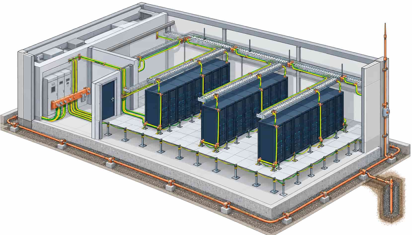
First, the earthing system itself: bare copper conductors in the ground and in the ring around the building, sized for fault current and corrosion life rather than ampacity tables. Second, the main bonding network: green-yellow insulated conductors that tie every metallic service — cable trays, ladder racks, water pipes, structural steel, raised floor pedestals where specified — into a single equipotential mass. Third, protective earth conductors running with power circuits, sized by the upstream protection device. Fourth, lightning protection conductors, designed to IEC 62305, which carry impulsive currents measured in tens of kiloamperes. Fifth, functional and EMC bonding — the clean reference conductors and mesh plates that data processing standards such as IEEE 1100 and the EN 50173 / ISO/IEC 11801 family expect for high-speed networks.
The five families share materials but not logic. An earthing ring conductor is chosen for corrosion-adjusted thermal withstand during a fault; a tray bonding conductor is chosen for continuity and mechanical robustness; a lightning down conductor is chosen for impulse current and the geometry of the down path. Specifying all of them as one generic “earth cable” line is the root cause of most grounding findings at inspection.
Sizes and Materials: The Working Numbers
Bare copper is the default electrode and ring material — copper tape or stranded bare copper conductor, typically 25 to 70 mm2 for building rings and electrode interconnections on mid-size facilities, with cross-sections verified against the prospective fault current and the clearing time of the protection. Green-yellow insulated bonding conductors on trays and structures are commonly 16 mm2 or 25 mm2 copper, enough to carry fault current between bonded sections without becoming the weak link. Protective earth conductors inside power cables follow the automatic-disconnection rules of the installation standard, which is why the cable schedule and the grounding schedule must be produced from the same load study — the logic of cross-section selection is shared with general cable size selection, even though the failure criterion differs.
Lightning protection is the arithmetic outlier. Down conductors per IEC 62305 start from a 50 mm2 copper minimum for most classes, and the real design work is geometric: multiple parallel down paths, separation distances from internal systems, and test joints for periodic measurement. Where the lightning system and the power earthing must interconnect — as they must in a unified design — the interconnection conductor inherits the lightning arithmetic, not the bonding arithmetic.
Connections: Where Grounding Systems Actually Fail
Conductor sizing gets the attention; connections earn the findings. A grounding system is a chain of terminations, and every joint is a potential open circuit. Mechanical bolted clamps are the workhorse for accessible bonding, but their long-term contact pressure depends on correct torque and on washers that bite paint and oxide layers. Exothermic welded connections — the CADWeld family — produce a molecular bond that cannot loosen or corrode, and they are the standard answer for electrodes, ring conductors and anywhere a joint will be buried or concrete-encased, at the cost of skilled execution per joint.
Compression connections occupy the middle ground: factory-controlled crimping with documented tooling, well suited to the repetitive tray bonding work of a large hall. Whatever the method, the specification should name it per application and require the installer’s records — torque logs, crimp die records, weld powder batch numbers. Data center floors hide their grounding under raised tiles and above suspended ceilings; a connection made undocumented is a connection that will be trusted for twenty years and verified never.
Bonding the Things Nobody Thinks to Bond
The inspection findings that recur across projects share a theme: conductors exist, continuity does not. Cable tray sections butted without bonding jumpers. Painted rack rails with the bonding conductor landing on the coating. Raised floor pedestals omitted from the bonding plan even though they are the most numerous metallic object in the hall. Screened cable glands left isolated from the tray they cross. Each is small; together they fragment the equipotential network the design assumed.
The remedy is a bonding schedule as explicit as the power cable schedule: every tray run, every rack row, every service penetration, with a conductor size and a connection method per item. On the structured cabling side, shield termination and bonding interact directly with signal integrity, a topic that crosses into the control and instrumentation cable territory where the EMC rules were worked out long before data halls adopted them. The upside of doing this properly is measurable — clean equalization references, predictable surge behavior and an audit trail the authority can sign without conditions.
| Application | Typical Conductor | Connection Method | Governing Reference |
|---|---|---|---|
| Earth electrodes and foundation ring | Bare copper tape or stranded, 25-70 mm2 | Exothermic weld; inspection pits at test points | IEC 62305-3; local earthing code |
| Building ring and interconnection to intake | Bare copper, fault-withstand verified | Exothermic or compression, torque documented | IEC 62305-3; IEC 60364-5-54 |
| Tray and ladder bonding jumpers | Green-yellow insulated copper, 16-25 mm2 | Bolted clamps with serrated washers; compression lugs | IEC 60364-5-54; project EMC plan |
| Rack row and cabinet bonding | Green-yellow insulated copper, 16 mm2 typical | Compression lug to prepared bare metal point | IEEE 1100; ISO/IEC 11801 bonding practice |
| Lightning down conductors | Bare copper, 50 mm2 minimum per class | Exothermic at electrodes; test joints for measurement | IEC 62305 series |
| Protective earth in power circuits | Sized with the circuit per installation standard | Within the cable; gland and lug per schedule | IEC 60364-4-41 / -5-54 |
Verification: The Numbers the Inspection Will Ask For
A grounding system is commissioned with measurements, not visual checks. Earth resistance at the electrodes or the combined system — the target depends on the design philosophy and the utility’s requirement, commonly at or below one ohm for data centers with sensitive equipment and surges to defend against, and in every case recorded against the design value. Continuity of the bonding network, measured end to end with a low-resistance ohmmeter. Every test joint in the lightning system read and logged. These numbers belong in the handover file next to the as-built drawings, because the maintenance regime — annual re-testing, thermographic survey of accessible joints, re-torque campaigns — is planned from the baseline.
Procurement can lock in verifiability by ordering from factories that treat grounding products as engineered items: bare copper conductor with documented cross-section and purity, sheathed bonding cable with consistently applied green-yellow compound, and exothermic kits matched to the conductor combinations actually used on site. Kexingyu Cable Group (KXYE) supplies bare copper earthing conductor and the full green-yellow bonding range alongside its power and control families, so the grounding schedule can be quoted, packed and certified with the same batch discipline as the rest of the cable scope. The verification mindset carries over from the equipment world — the same logic that separates factory acceptance testing from site acceptance testing applies to a grounding package, where the measurable evidence is produced before the tiles go down. Where the grounding package is quoted with the power scope under one copper price linkage, the whole order shares one commercial basis through the project schedule.
| Recurring Finding | Consequence if Missed | Prevention in the Specification |
|---|---|---|
| Tray sections not bonded across joints | Fragmented equipotential network; surge and EMC exposure | Bonding jumper size and spacing stated per tray type, listed in the bonding schedule |
| Bonding landed on paint or anodizing | High-resistance joint hidden under a tidy appearance | Connection points defined as prepared bare metal; torque records required |
| Undersized interconnection between lightning and power earth | Side-flash risk and failed lightning inspection | Interconnection sized by IEC 62305 arithmetic, not by the bonding table |
| Test joints omitted or unreachable | Lightning system cannot be periodically measured | Test joint locations drawn on as-builts; accessibility checked at FAT-style walkthrough |
| Raised floor pedestals excluded from bonding plan | Largest metallic population in the hall left floating | Pedestal bonding method and conductor named; count verified at commissioning |
When a Generic Grounding Line Item Is Not the Answer
The tempting shortcut is to price grounding as one lump sum per square metre. The economics collapse at the first design change: rack rows move, tray routes grow, and the lump sum becomes a negotiation rather than a schedule. A grounding package priced from the bonding schedule survives change orders because every conductor has a home.
The second trap is importing another project’s earth resistance target. A one-ohm target makes sense where surge protection and sensitive electronics justify the electrode effort; enforcing it on a site with deep-driven-well economics may spend the grounding budget twice over for no measurable benefit, while an underdesigned target on a high-lightning-exposure site buys findings instead of safety. The number comes from the site’s soil resistivity survey and the protection design — not from habit. Where the earthing scope meets the MV intake, the utility’s requirements and the substation design also enter the arithmetic, as we describe in the compact substation reference for data centers.
RFQ Checklist: Ordering the Grounding Package
- Soil resistivity survey results and the target earth resistance value from the design
- Electrode and ring schedule: conductor sizes, total lengths and burial depths
- Bonding schedule by element: tray runs, rack rows, pedestals, service penetrations
- Conductor types: bare copper sizes, green-yellow insulated bonding sizes, lightning down conductors
- Connection methods per application: exothermic, compression or bolted, with hardware
- Test joint locations and the measurement regime expected at handover
- Standards and editions: IEC 62305 class, IEC 60364-5-54, project EMC plan
- Material certificates: copper purity and cross-section documentation per delivery
- Third-party inspection scope where the project warrants it
- Pricing basis and validity, with copper price linkage where the order scales with the project
A supplier who answers those ten lines in schedule order is a supplier who has built data center grounding before.
Conclusion
Grounding and bonding cable is a small percentage of the copper in a data center and a disproportionate share of its inspection risk. The specification that succeeds names five conductor families separately, sizes each for its own failure mode, fixes the connection methods, and demands the measurements that prove the network is continuous.
Build that specification once and it becomes a reusable asset across every hall you deliver. When you are ready to price it, Kexingyu Cable Group (KXYE) quotes the grounding package — bare copper earthing conductor, green-yellow bonding cable and the associated power and control families — from one factory group with batch certification and export documentation. Send the bonding schedule and soil survey, and we will return a line-by-line offer.


