
Cable Planning for 30kW+ AI Racks: Density Is the New Problem
Quick Answer: A 30kW AI rack multiplies feeder current and grouping derating, not just cable count — high-density rack cabling must be planned per route with real ampacity inputs. Ten years ago a well-provisioned enterprise rack drew 5 kW and nobody argued about cable. Today AI clusters routinely specify racks at 30 kW and above, and the conversation has moved from server specifications to the unglamorous layer underneath: how many feeders, how large, routed where, and derated by how much. Cable planning is where density projects quietly succeed or stall.
Introduction
Rack density is climbing faster than hall floor space, which means the same aisles must now carry three to six times the current they were designed for. Industry surveys from Uptime Institute and the leading market analysts keep revising average and peak rack densities upward as AI training clusters displace general-purpose rows — part of the same buildout wave we track in data center power demand growth. Meanwhile, modular data center lines aimed at AI workloads now ship racks rated at 18 kW and higher as standard, confirming that high density has moved from exception to baseline.
This article converts that density shift into cable decisions: what a 30 kW rack does to feeder sizing, how grouping and ambient corrections reshape the cable schedule, where busway versus parallel cable feeders each win, and what the RFQ must say so the factory prices the real duty rather than the nominal one. The equipment side of the same power chain — switchgear, UPS, transformers — is covered in our data center power collection.
What 30 kW per Rack Actually Means for Cable
At 415/240 V three-phase, a 30 kW rack at typical power factor draws roughly 45-50 A per phase — manageable at first glance. The difficulty is not the single number but everything around it. A row of twenty such racks concentrates around 1,000 A of continuous load on the row feeder, and the variety inside the row matters: racks do not peak simultaneously, but cable cannot be sized on hope. Diversity factors, redundancy mode and future headroom all enter the feeder calculation before any correction factor is applied.
Then the corrections begin. Overhead trays above hot aisles routinely see 40-50 °C ambient; grouped circuits in shared trays derate each other; and containment filled to 80% capacity behaves nothing like the tidy single-circuit diagram in the design software. A 50 A route that looks fine as a 10 mm² cable on paper can need 16 mm² or 25 mm² after real grouping and ambient factors — and across two hundred racks, that difference rewrites the entire copper order. The method for turning a load schedule into corrected cross-sections is walked through in our cable size selection guide.
| Rack Density | Typical Feeder Arrangement | Cable Families Involved | Planning Note |
|---|---|---|---|
| 5-8 kW | One branch circuit per rack, 16-25 mm2 | LV distribution, structured cabling | Legacy design; trays sized with generous spare capacity |
| 10-15 kW | One 32-63 A circuit or dual feeds per rack | LV distribution, LSZH wiring | Grouping derating starts to matter in shared trays |
| 20-30 kW | Dual A/B feeds, 25-50 mm2, or busway tap-off per rack | LV distribution, LSZH, bonding | Row feeder reaches 800-1,000 A; tray fill becomes the constraint |
| 30-60 kW+ | Busway spine with tap-off boxes, or parallel single-core sets | LV distribution, flexible connections, bonding | Termination flexibility and heat rise drive Class 5 stranding |
| 100 kW+ (NVL-class) | Row-level busway plus dedicated high-amperage feeders | LV distribution, control, bonding | Cable routes converge with cooling plant routes; coordinate early |
Busway Hand-Off or Parallel Cable Feeders
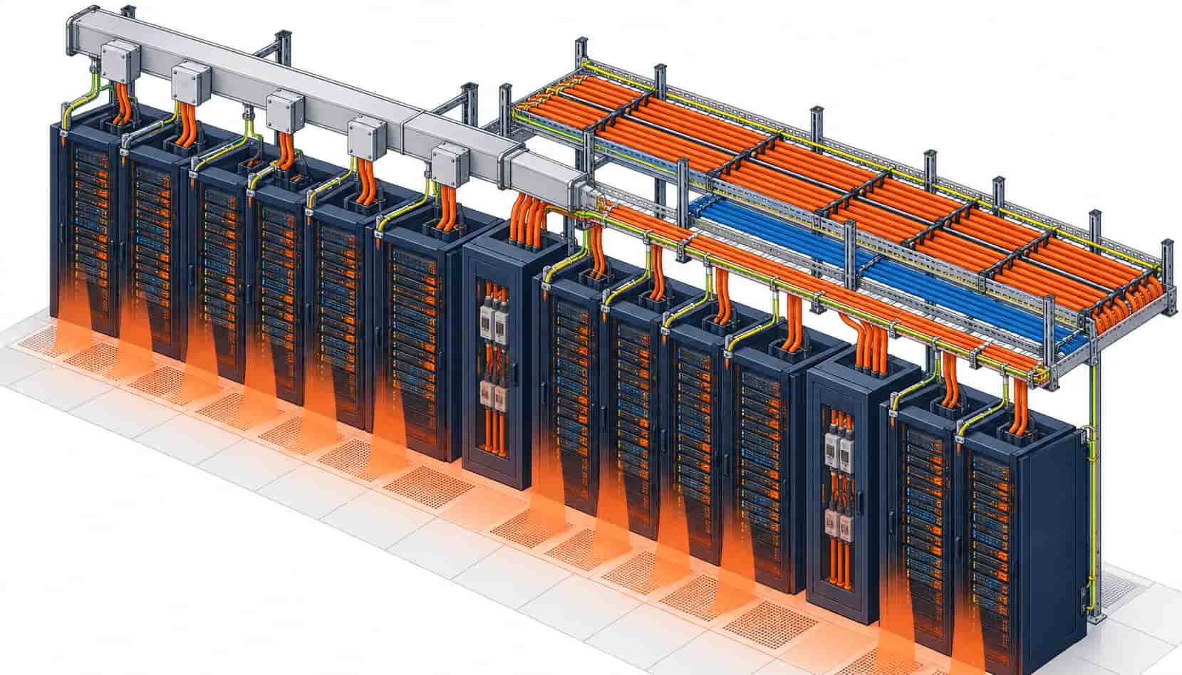
Above roughly 20 kW per rack, most designers stop running individual branch circuits from a distant panel board and bring a busway spine down the row instead. The busway concentrates one high-amperage run overhead and hands off to racks through tap-off boxes, which cuts tray congestion and makes rack additions a plug-in operation rather than a pulling operation. The trade-off between the two approaches — where each one wins on cost, flexibility and installation time — deserves its own evaluation in every project, because retrofit constraints often decide it before economics do.
Where parallel cable feeders remain the choice — retrofits, lower-density edges of the row, or budgets that favor cable — the specification rules tighten. Parallel single-core sets need identical lengths per phase to force current sharing, non-magnetic containment on single-core AC runs, and Class 5 flexible stranding where the set lands on a PDU or rack PDU input. Insulation stays XLPE across these sizes because the 90 °C continuous rating is what keeps conductor sizes sane once derating is applied — the chemistry behind that rating is explained in what XLPE cable is and how it works.
Tray Congestion Is the Real Bottleneck
The binding constraint in high-density halls is rarely ampacity arithmetic; it is physical space. Power trays, copper network trays, fiber troughs and bonding conductors all compete for the same overhead corridor, and liquid cooling retrofit adds coolant piping to the fight. A hall designed for 8 kW rows has trays sized for a cable population that a 30 kW rebuild triples. Planning responses that work: segregate power and data by distance or shielding from the start, reserve a spare tray position per route for future density increases, and treat every tray fill calculation as a living document reviewed at each density bump.
Congestion also feeds back into electrical design. More circuits per tray means more grouping derating, which means larger conductors, which means deeper trays — the loop only terminates when someone plans it deliberately. This is why mature specifications state tray fill percentages and spacing rules in the cable schedule itself, not just in the installation standard, and why the routing method (tray, duct, direct buried) is part of every RFQ line.
PDU and Rack-Level Connections
Below the row feeder, the last metres carry their own rules. Floor-standing PDUs take large flexible feeders — frequently 50-95 mm² Class 5 — while rack-mounted PDUs draw from busway tap-offs through short flexible assemblies. The choice between floor and rack PDU architecture changes the cable population at the rack, and the practical differences are laid out in rack versus floor mounted PDU selection. Flexible connections at this level see vibration and frequent rework, so fine-stranded conductors with high-flex insulation and robust strain relief outlast ordinary building wire even at equal ampacity.
UPS-side cabling closes the loop. High-density rows backed by centralized UPS plant load the same UPS output feeders that sized the medium-density design — but at three times the current. Our guide to UPS sizing for data centers covers the load side of that recalculation; the cable side is the same discipline of corrected ampacity with shorter, hotter routes.
| Planning Item | Recommendation | Specification Anchor |
|---|---|---|
| Rack feeder sizing | Size per route with real grouping and ambient, not nameplate current | IEC 60364-5-52 correction factors documented per route |
| Row distribution | Busway spine above 20 kW/rack; parallel single-core sets elsewhere | Identical set lengths; non-magnetic containment on AC single-core |
| Conductor stranding | Class 5 flexible for PDU and tap-off connections | IEC 60228 Class 5; 90 °C XLPE insulation |
| Tray segregation | Power/data separation plus one spare tray position per route | Project EMC plan; tray fill percentage stated in schedule |
| Sheath material | LSZH throughout technical rooms and hot aisles | IEC 60332-3; IEC 60754-1; IEC 61034-2 |
| Future density | Size containment and feeders with one density bump of headroom | Diversity and growth factors named in the load schedule |
When a Density Retrofit Is Not Just a Cable Order
Not every hall should chase 30 kW racks. If the upstream switchgear, transformer capacity and cooling plant were sized for a medium-density design, lifting rack density without an upstream study simply relocates the bottleneck from the rack to the row feeder or the UPS output — and a cable upgrade cannot fix a transformer that is already at its limit. The honest sequence runs upstream first: confirm capacity at the switchboard, verify protection settings for the new load profile, then resize the cable layer.
There is also a point where repeated retrofits cost more than a rebuilt row. When tray replacement, feeder upsizing and PDU swaps all land in the same aisle within a maintenance window, the integrated skid and prefab approaches become cheaper than staged field work — a trade-off examined in planning around switchgear and equipment lead times, where factory-integrated delivery shortens the same critical path.
RFQ Checklist: Ordering Cable for a High-Density Hall
High-density cable orders fail on missing assumptions, so the RFQ should carry the density context explicitly:
- Row elevation or PDU one-line showing feeder topology and A/B redundancy mode
- Per-route design currents with the grouping and ambient correction factors already applied
- Busway interface points and tap-off ratings where the hand-off strategy is fixed
- Parallel set requirements: identical lengths, phase arrangement, containment type
- Class 5 flexible stranding on all PDU and rack-level connections
- LSZH sheath class and flame spread category for technical room routes
- Tray fill data or routing method per route (tray, duct, direct buried)
- Drum lengths matched to pulling plans, including any mid-route joints to avoid
- Batch test reports with conductor resistance evidence per shipment
- Copper price linkage terms to hold the budget across the build schedule
That last line earns its place twice in dense projects. Copper is the dominant cost driver in power cable, and a 200-rack hall orders tonnes of it; a supplier who quotes against a copper price linkage keeps the approved budget valid between order and delivery, which matters more as density multiplies the quantity exposed to the metal market.
Conclusion
High density rack cabling is a planning problem before it is a product problem. A 30 kW rack changes feeder topology, derating inputs, tray population and the busway-versus-cable decision all at once, and the projects that absorb the change cleanly are the ones that recalculated per-route ampacity with real inputs and reserved physical space for the next density bump.
If you are re-planning a hall for AI-class racks, send the load schedule and row elevations to Kexingyu Cable Group (KXYE). We size and quote the full LV distribution scope — parallel single-core sets, flexible Class 5 assemblies, LSZH feeders and bonding — against the named standards, with copper price linkage for project-scale orders, and return a line-by-line offer that matches the density you are actually building.


