
AGV Charging Cable Design: Contact Wear, Duty Cycle and Safety
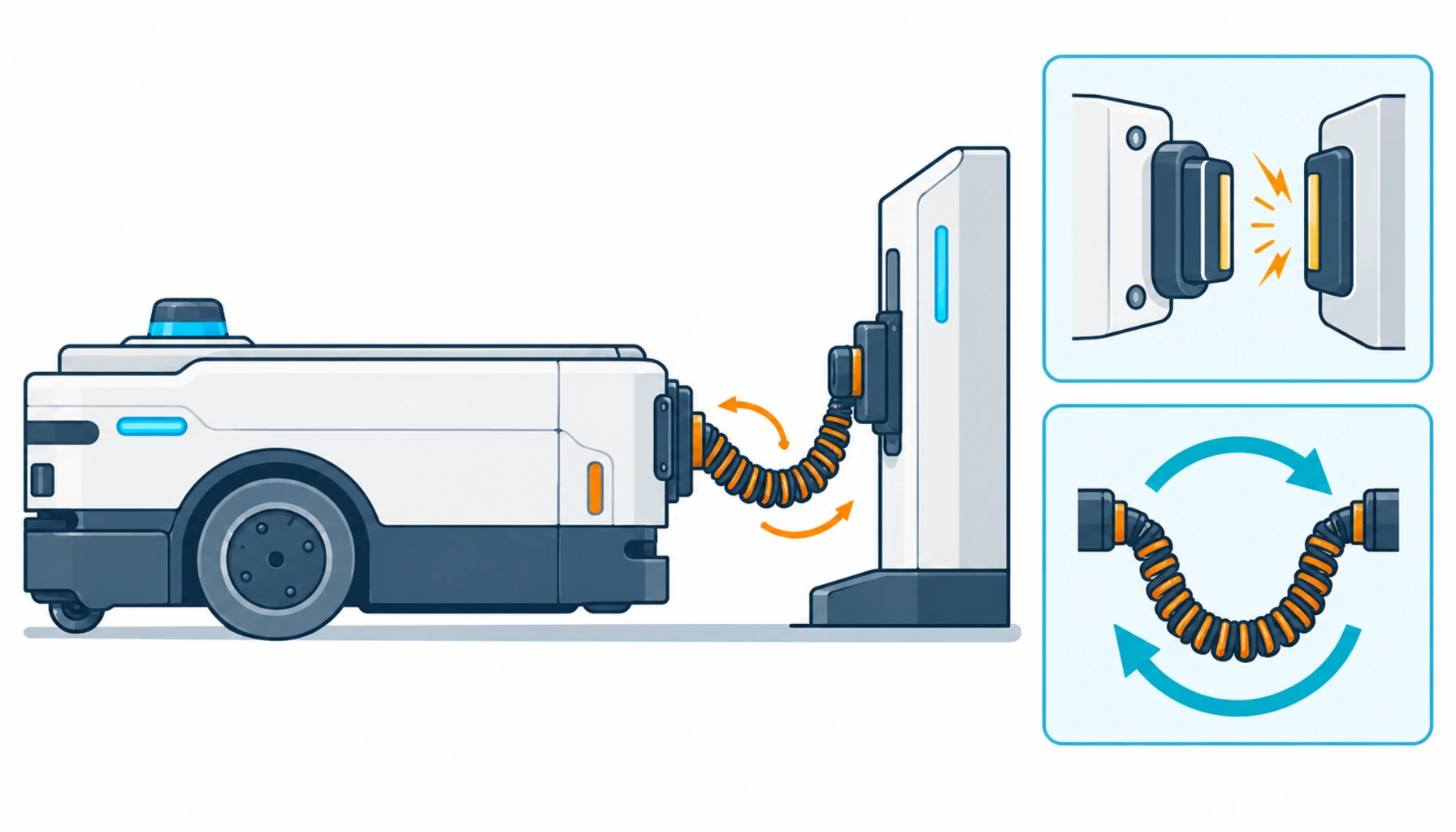
Quick Answer: An AGV charging cable survives hundreds of high-current dockings a day — coiling, contact force and current spikes at every plug-in — so its construction, routing and safety wiring are engineered, not inherited from a power cord.
Charging is where a mobile fleet meets the electrical system, and it is the most under-engineered circuit on most AGV projects. The vehicle side gets the attention — batteries, controllers, navigation — while the charging cable is treated as an accessory until the first charger starts tripping ground faults in month eight. The duty is brutal in an unglamorous way: opportunity charging means a vehicle docks, ramps to full current for ninety seconds, undocks, and repeats that several hundred times a day. Multiply by a fleet of forty and the charging circuit completes more connect-disconnect-flex cycles in a month than a machine tool cable sees in a year. This guide walks through what that duty does to cable construction, to contacts, and to the safety wiring that has to keep working while everything around it wears.
Introduction
Three charging architectures dominate mobile fleets, and each one loads the cable differently. Manual or semi-automatic charging uses a connector an operator or a coupler mates on schedule. Opportunity charging docks the vehicle automatically at stations scattered along its route, topping the battery in short bursts. Fully automatic charging uses spring-loaded paddles or docking heads on the vehicle that mate with station contacts without human help — increasingly the default for high-throughput operations because the fleet never stops to wait for a charge. Inductive pads remove the cable from the vehicle side entirely, at the cost of efficiency and installation budget.
Whatever the architecture, one electrical fact is constant: the charging circuit carries battery-scale current through components that cycle mechanically all day long. The chemistry in the pack shapes the current curve — the charge profiles behind LiFePO4 and competing chemistries differ in acceptance current and taper behavior — but every architecture asks the cable, the contacts and the interlock wiring to survive a duty profile that no stationary installation matches. Sizing the circuit from a wallbox mindset is how fleets end up with melted contacts and unexplained charger faults.
The Four Charging Methods and What They Ask of the Cable
Before specifying anything, be clear about which charging world the fleet lives in. The four methods below cover nearly every installation, and their cable requirements differ by an order of magnitude.
| Method | How It Works | Cable Duty Profile | Design Focus |
|---|---|---|---|
| Manual connector | Operator plugs the vehicle in on schedule, usually overnight | One or two cycles a day; long idle at full bend on the connector | Connector strain relief; jacket memory at the plug; lockout wiring |
| Opportunity charging | Automatic short top-ups at stations along the route | Hundreds of dock-and-flex cycles per vehicle per day at high current | High-flex conductor stranding; coil-memory-resistant jacket; contact rating |
| Automatic docking | Spring paddles or heads mate without human help | Full-current make-and-break through contacts several hundred times a day | Contact material and force; arc mitigation; interlock loop integrity |
| Inductive pad | Contactless power transfer through a floor or bumper pad | Minimal vehicle-side cable motion; station-side fixed wiring only | Station wiring and cooling; alignment tolerance; efficiency losses |
Contact Wear: The Part Everyone Underestimates
Contacts are consumables, and the cable design either respects that or fights it. Every docking event is a make-and-break under load potential: misalignment, dust and contact bounce create micro-arcing, and each arc erodes a little plating. Left alone, contact resistance creeps up, contact temperature follows it, and eventually the charging station starts faulting on over-temperature or the connector shows visible pitting. The cable side contributes in two ways. First, harness compliance: if the cable is stiff or routed without slack, docking misalignment transfers force straight into the contacts instead of being absorbed by the loom, and wear accelerates. Second, terminal quality: a crimp that runs warm adds its own resistance to the contact chain, and the two heat sources multiply.
Practical fleet discipline treats the charging circuit as a wear system with scheduled inspection. Contact resistance logged over time shows the creep before it becomes a fault. Cable terminals re-torqued and thermally checked at service intervals catch the warm-crimp problem early. And the cable construction itself should be specified with fine stranding and a jacket that does not propagate cracking from the connector back down the loom — the same failure-at-the-transition pattern documented in the common causes of cable failure, appearing this time at a charging paddle instead of a gland.
Duty Cycle: Why Opportunity Charging Changed the Cable Business
Overnight charging let everyone spec charging circuits like extension cords. Opportunity charging destroyed that comfort. When a vehicle docks three hundred times a day, the charging cable completes a full flex cycle at its service loop for each docking — and flex life, not ampacity, becomes the binding constraint. The service coil is the critical element: a cable that coils on itself thousands of times a week develops a memory set, then cracks at the same point of every bend. High-flex constructions with short-lay stranding and jacket compounds that resist set are what turn a ninety-second top-up from a consumable event into routine operation.
Current behavior during the cycle matters as much as cycle count. Charge acceptance tapers as the pack fills, but the first seconds at the dock can pull near-maximum current through contacts that are still seating. Ramping electronics soften this, and the cable and terminals need to be rated for the peak, not the average. Thermal cycling does the rest: a harness that heats at every dock and cools between them fatigues faster than one held at a steady temperature, which is why conductor sizing headroom pays for itself here even though average current looks modest.
Safety Circuits: The Wiring That Must Outlive the Wear
Every charging architecture carries a safety layer alongside the power conductors: interlock loops that confirm the vehicle is docked before current flows, ground-fault and insulation monitoring, temperature sensing at the contacts, and emergency-stop circuits that span the charging bay. These circuits are low-energy, which makes them easy to treat as signal wire — and dangerous to do so, because a safety cable that fails intermittently disables protection precisely when nobody is looking. The interlock loop through a docking head flexes at every cycle just like the power conductors beside it; it needs motion-grade construction, braid shielding where the charging environment is electrically noisy, and routing that keeps it away from the contact heating zone.
The safety case extends beyond the cable. Charging bays concentrate battery energy, and the lithium-era hazards — the mechanisms behind thermal runaway in lithium batteries — make early detection wiring at the charger and dock worth its installation cost. Certification expectations belong in the specification too, since charging equipment and its wiring fall under the same documentation discipline outlined in the electrical equipment certification checklist. A charging system whose power cable is robust but whose safety loom was bought on price has simply scheduled its worst failure for the least convenient moment.
| Check | What to Pin Down | Why It Decides the Outcome |
|---|---|---|
| Dockings per day | Cycles per vehicle, current at plug-in, ramp profile | Sets flex life targets and contact rating before anything else |
| Service loop geometry | Coil radius, slack length, fixed-end positions at dock and chassis | Flex failures concentrate at the coil memory point and the gland |
| Compliance at dock | Slack and strain relief absorbing docking misalignment | Stiff harnesses transfer force into contacts and accelerate wear |
| Termination quality | Crimp spec, torque values, thermal check points in the maintenance plan | A warm terminal adds resistance to the contact chain and hides there |
| Safety loom construction | Interlock, ground-fault and temperature wiring rated for the same flex duty | Protection that fails intermittently is worse than none |
| Inspection schedule | Contact resistance trend, jacket check at the coil, terminal thermography | Wear systems are managed by data, not by waiting for the fault |
When Charging Cable Rules Are Not the Answer
Honesty about scope keeps this guide useful. Everything here addresses the cable between the charging infrastructure and the vehicle — the flexing, docking, wearing part of the circuit. It does not cover the stationary installation behind the charger: feeders from the distribution board, the protection and grounding design for the charging lane, and the building-side wiring codes that govern them are electrical installation work governed by local code and the project engineer of record. Inductive systems shift most of the interesting engineering into the pad and its power electronics, where cable questions largely become station wiring questions. And battery management — charge curves, balancing, thermal supervision — is the BMS engineer’s territory; the cable delivers current, it does not decide how. Keep those boundaries straight and the charging circuit stops being the fleet’s mystery failure.
RFQ Checklist: What to Send the Charging System Supplier
Put the fleet’s charging reality in writing before quotes come back:
- Charging architecture: manual, opportunity, automatic docking or inductive — with dockings per vehicle per day
- Electrical data: voltage, peak and average current, ramp profile, battery chemistry and its charge curve
- Dock geometry: alignment tolerance, service loop space, fixed-end positions at chassis and station
- Environment: temperature band, dust, moisture, washdown zones, outdoor exposure at the dock
- Safety scope: interlock loop, ground-fault monitoring, contact temperature sensing, bay e-stop wiring
- Flex life requirement with the test method that will verify it
- Spares and inspection: contact sets, pre-terminated charging looms, resistance trending plan
Conclusion
An AGV charging cable lives the hardest duty on the fleet: full current, hundreds of make-and-break cycles a day, and a safety layer that has to keep working while everything around it wears. Fleets that engineer the circuit — flexible construction, compliant routing at the dock, monitored contacts, motion-grade safety looms — get charging infrastructure that disappears into the background. Fleets that spec it like an extension cord meet it in the fault log instead.
Kexingyu Cable Group (KXYE) supplies high-flex cable constructions for charging circuits and supports integrators with duty-based selection, batch traceability and honest cycle ratings. Describe your charging architecture and docking duty through the RFQ page, and we will match constructions to the circuit — including the safety looms most quotes forget.


