
Welding Robot Cells: Cable Solutions for Heat, Spatter and EMI
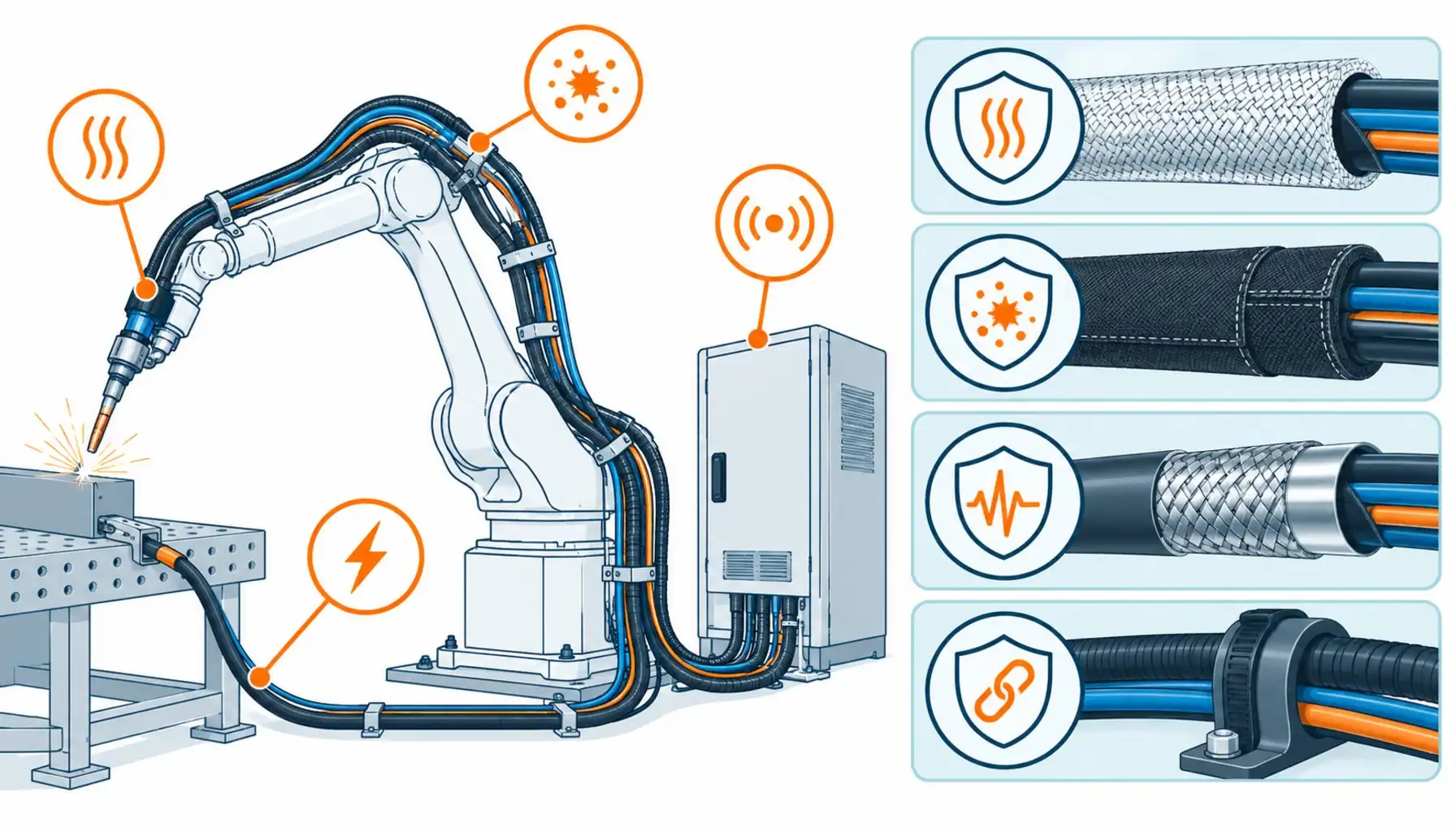
Quick Answer: A welding robot cell attacks cable four ways at once — torch-side heat, molten spatter, millions of arm cycles and the noisiest electrical environment in the plant — so every circuit needs protection matched to its zone.
Ask a maintenance crew which robot application eats the most cable and the answer is almost always the same: welding. The cell combines four hostile factors that rarely coexist elsewhere. The torch package works at temperatures that would cook any ordinary insulation. Molten spatter lands on everything within a meter of the arc, including the dress pack riding the robot arm. The arm itself flexes its harness through millions of cycles with a payload swinging at the wrist. And the welding process is one of the most violent electrical events in industry — hundreds of amps switched at high frequency, a few meters from the control signals that run the cell. Cable failures in welding cells do not just stop one robot; they stop the cell, and in automotive-style production, the line behind it. This guide maps each cable circuit in a welding cell against its actual exposure, and lists the specification decisions that turn the dress pack from a weekly consumable into a system component.
Introduction
A robotic welding cell looks simple from outside — a robot, a torch, a positioner, a fence. Inside, it is one of the densest wiring environments in manufacturing. The torch carries power, gas, cooling water and wire feed control to the wrist. The robot arm’s internal dress pack carries servo power, feedback and process signals through every joint. The work return circuit carries the full welding current back from the part. Positioners and fixtures add their own motor and sensor circuits. And the cell controller ties everything together with safety loops and fieldbus. Every one of these circuits has a different enemy, and the classic mistake is protecting them all the same way — usually by wrapping everything in the same sleeve and hoping.
The hope fails in predictable places. The failure patterns documented in the common causes of cable failure — breaks at transitions, jacket degradation, shield damage — all appear in welding cells, accelerated by heat and spatter. The cells that run reliably treat the cable system as zoned engineering: each circuit specified against its own exposure. That zoning discipline is what this guide lays out.
The Zones of a Welding Cell and What Each Does to Cable
Zoning is the organizing idea. The exposure at the torch is not the exposure on the arm, and neither is the exposure at the cell controller. Specifying by zone keeps the protection where it pays.
| Zone | Exposure | Circuits Running Through | Protection That Works |
|---|---|---|---|
| Torch package | Arc heat, spatter at the source, constant wrist motion | Welding power, gas, cooling water, wire feed control | Integrated torch cable assemblies; heat-resistant sleeves; correct dressing at the wrist |
| Dress pack (arm) | Spatter shower, abrasion on structures, millions of joint cycles | Servo power, encoder feedback, process and safety signals | Corrugated conduit with spatter shields, abrasion sleeves at contact points, motion-grade cable inside |
| Work return and fixtures | Full welding current, spatter, mechanical abuse from clamping | Ground return, fixture sensing, positioner drives | Oversized return lugs, protected routing, abrasion armor at clamp points |
| Cell controller side | EMI from the weld power circuit, ordinary shop environment | Fieldbus, safety loops, HMI and cell I/O | Shielded cables with disciplined grounding, separation from power runs, filtered entries |
Heat: The Enemy at the Torch End
The torch package lives with radiated and conducted heat that degrades ordinary insulation in weeks. Welding power conductors in the torch cable assembly are built for it — heat-rated insulation, compact construction, and cooling water jackets where the process demands them. The specification point that matters most is the dressing at the wrist: where the torch assembly leaves the dress pack and bends toward the work, every cycle flexes the assembly at a fixed point while it is hot, and hot flexing multiplies fatigue. Heat-resistant sleeves and correct minimum bend radius at that transition extend torch cable life dramatically. The compound physics behind jacket selection under heat — and why insulation chemistry matters more as duty rises — follows the same logic as the XLPE versus PVC comparison: the material that holds its properties at temperature is the one that survives the arc’s neighborhood.
Spatter: Abrasion With a Temperature
Molten spatter is abrasion with heat attached. Beads land on the dress pack, stick, and either burn through the outer layer or sand it off as the arm moves. The dress pack’s outer protection — corrugated conduit plus spatter shields at exposed sections, abrasion sleeves wherever the bundle touches structure — takes the beating so the cables inside do not have to. Three details separate protected cells from consumable ones. First, coverage where it matters: the wrist region and any section facing the arc take the most hits, and shields belong there, not distributed evenly for appearance. Second, the wear items are designed to be replaced: sleeves and shields are consumables by design, and a cell that treats them as maintenance items with a schedule outlives a cell that discovers them by failure. Third, what is inside the protection still counts: a motion-grade cable under the conduit ages slowly even when the armor is chewed, while a cheap cable under perfect armor still fatigues at its glands — a reminder that the armored-versus-unarmored logic in armored cable selection applies to robot dress packs too.
EMI: The Invisible Enemy at the Cell Level
The welding arc is a switching event of hundreds of amps with steep edges, and its power circuit couples noise into every unshielded circuit in the cell. The victim list is familiar: encoder feedback on the robot and positioners, fieldbus segments, sensor lines, safety loops that must stay hard-wired and clean. The defenses are the standard power-versus-signal discipline from control and instrumentation wiring — braid shields with proper grounding at one end, physical separation from the weld power run, filtered cabinet entries — applied with extra rigor because the noise source is so aggressive. Cells that skimp on this produce a signature fault: the robot pauses or glitches exactly when the arc strikes, and no one can reproduce it with the welder off. That fault pattern is a shielding and grounding audit waiting to happen, and it costs more diagnostic time than the shielded cable ever cost.
Motion: The Dress Pack Between the Joints
Welding robots move differently from machine tools — shorter strokes, more joints, continuous reorientation — and the dress pack rides all six axes at once. The cable inside still follows motion-grade construction: fine stranding, strain-carrying cores, braid shields rated for flexing. The routing is where welding cells differ from cleaner applications: the bundle must clear every structure it passes, with abrasion protection at every predicted contact point, because spatter-damaged sleeves plus a rubbing contact point is the standard recipe for a through-the-jacket fault. Cells with the best dress pack life route generously — larger bend radii, standoff clips, contact points identified and armored — instead of pulling everything tight to look tidy on delivery day.
| Check | What to Pin Down | Why It Decides the Outcome |
|---|---|---|
| Process parameters | Welding current, duty cycle, torch type, cooling method | Sets the electrical and thermal rating for torch-side circuits |
| Spatter exposure map | Which dress pack sections face the arc, with hit frequency | Shields and sleeves go where the beads land, not everywhere |
| Arm duty | Cycle profile, wrist motion range, dress pack routing and clearances | Flex life and abrasion points are decided by routing, not by cable brand |
| EMC plan | Shielding, grounding and separation between weld power and signals | Arc-strike glitches are prevented here or debugged for months |
| Work return sizing | Return conductor and lug capacity for full weld current | An undersized return heats, drops voltage and corrupts the arc |
| Consumables plan | Sleeve and shield replacement schedule, spare torch assemblies | Protected cells treat wear items as maintenance, not surprises |
When Welding Cell Rules Are Not the Answer
Honesty about scope keeps this guide useful. The zoning logic here addresses robotic arc and resistance welding cells — the machines where heat, spatter, motion and EMI combine. It does not cover the welding power source itself or the plant’s supply to it, which follow power equipment engineering on the supply side. Manual welding stations have their own cable practice, driven by operator handling rather than robot motion. Foundry and cutting applications push heat beyond welding-cell levels and need their own protection classes. And the general robot cable questions — joint construction, flex life, dress pack design on non-welding arms — are covered by the standard robot cabling guides rather than the welding-specific layers here. Match the protection to the actual exposure, and the specification stays both honest and affordable.
RFQ Checklist: What to Send the Integrator or Cable Supplier
Put the cell’s reality in writing before quotes come back:
- Process data: welding current, duty cycle, torch package type, cooling method
- Robot model and arm routing: dress pack path, joint motion range, cycles per hour
- Spatter map: sections facing the arc, with expected hit frequency per shift
- EMC plan: weld power routing, shielded circuit inventory, grounding scheme
- Work return: full current path including fixtures and positioners
- Consumables: which sleeves, shields and torch assemblies are planned maintenance items
- Proof: flex and heat test data, batch traceability, spare dress pack sets on the shelf
Conclusion
Welding cells fail cable by combination, not by any single enemy: heat at the torch, spatter on the arm, EMI at the controller, motion everywhere. Cells that zone the problem — protecting each circuit against its own exposure, treating wear items as maintenance, and taking EMI seriously at the design stage — run dress packs for years instead of weeks. The cable specification is where that zoning either happens or gets paid for later.
Kexingyu Cable Group (KXYE) supplies motion-grade cable constructions for robotic cells and supports integrators with zoned specifications, heat-rated compounds and shielded signal cables — with batch traceability behind every rating. Describe your cell through the RFQ page, and we will respond with protection mapped to each zone rather than one wrap for everything.


