
Camera and Vision System Cables on Moving Machinery: Signal Integrity at Speed
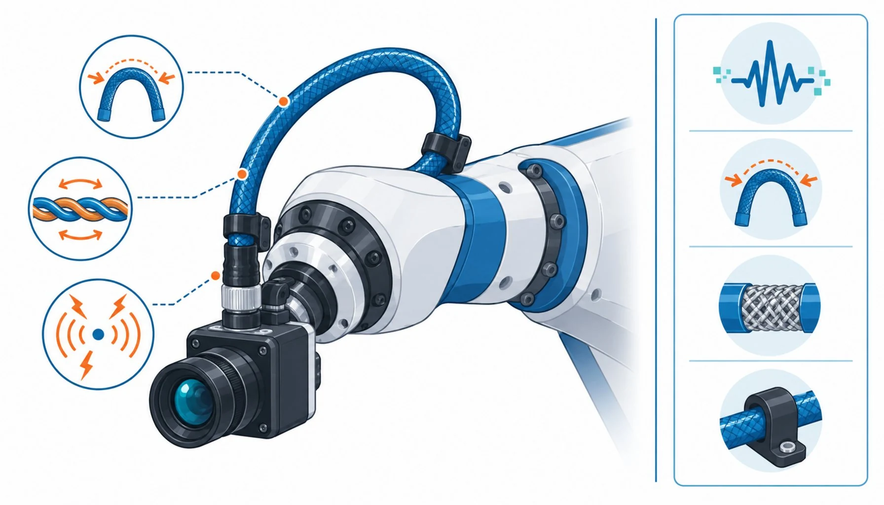
Quick Answer: A vision cable on moving machinery carries a high-bandwidth digital signal through constant flexing — and when images drop or cameras ghost, the cause is usually cable construction, bend radius or EMI, not the camera software.
Machine vision has quietly become the quality department of modern manufacturing — inspecting parts, guiding robots, reading codes at line speed. And the most common vision complaint in moving applications has an equally quiet cause: the cable. A camera on a robot wrist or a moving carriage streams hundreds of megabits through a cable that flexes with every motion, sits centimeters from servo drives and motor power, and gets blamed for nothing until the day images start dropping. Then the debugging begins in software, where it will stay for weeks, because a signal that degrades gradually looks exactly like a system that is flaky. The truth is blunter: a vision cable in motion is a precision signal component, and it fails by the rules of signal integrity, not the rules of power wiring. This guide covers what moving vision cables carry, why they fail, and the specification that keeps images streaming for the life of the machine.
Introduction
The electrical demands are easy to underestimate. Modern industrial camera interfaces push serious bandwidth: GigE Vision over Ethernet at gigabit rates and beyond, CoaXPress over coaxial structures at several gigabits, Camera Link over paired conductors, USB3 in compact applications. Each of these depends on controlled impedance geometry — the physical spacing and symmetry of the conductors — and each degrades predictably when that geometry is disturbed. Flexing disturbs it. Bending at too tight a radius disturbs it. Noise coupled from nearby power circuits disturbs it. None of the disturbances produce a clean failure; they produce timing errors, retransmissions, corrupted frames — symptoms that software teams inherit as mystery bugs.
The motion context makes all of it worse. A vision cable on a robot wrist or a moving axis lives the same flex life as any motion cable — millions of cycles — while carrying a signal far less forgiving than motor current. The failure habits of common cable failure apply, with signal integrity added as the first casualty. The engineers who run reliable vision systems treat the cable as part of the optical path: specified, tested and routed with the same care as the lens.
The Cable Types and What Motion Does to Each
Each camera interface has a different physical structure, and motion attacks each one differently.
| Interface | Physical Structure | What Motion Damages First | Specification Response |
|---|---|---|---|
| GigE Vision (Ethernet) | Four twisted pairs with controlled impedance, overall shield | Pair geometry distortion from flexing; shield rupture from cycle fatigue | Flex-rated industrial Ethernet construction; bend radius discipline; braid shields |
| CoaXPress | Coaxial core with precise center-conductor geometry | Center conductor migration and impedance drift at tight radii | Flex-rated coax with motion-tested construction; generous loop radius |
| Camera Link | Multiple twisted pairs, large bundle, overall shield | Bundle stiffness — largest cable, tightest routing pressure | Flex-rated versions only; route with the largest radius available |
| USB3 / compact interfaces | Thin paired conductors, small diameter | Connector strain — small cables get pulled and crimped at the camera | Strain relief at the camera; motion-rated construction despite the size |
| Trigger and I/O lines | Simple paired or multiconductor, low bandwidth | Intermittent opens that mistime acquisitions | Same flex rating as the data cable — the trigger fails silently |
Why Vision Cables Fail in Motion
Three mechanisms dominate, and all three are specification problems before they are field problems.
Geometry distortion. Twisted pairs and coaxial structures hold their electrical properties only while their physical geometry holds. Flexing at excessive radius, crushing against structure, or repeated bending at one memory point changes the pair spacing and the impedance along the cable. The signal does not stop — it reflects, jitters and drops frames intermittently, usually worse at speed or temperature extremes. Flex-rated constructions use bonded pairs, compact profiles and short-lay twisting to hold geometry through motion; ordinary office-grade cable holds it until the first thousand bends.
Shield failure. The shield is the vision cable’s immune system, and it lives in the noisiest neighborhood on the machine: servo drives and motor cables switching kilowatts centimeters away. A braid shield that survives flexing keeps that noise out; a foil shield cracks within weeks of motion and the image stream inherits the interference — dropped frames that correlate with axis motion, banding that moves with machine speed. Shield discipline, grounding and separation from power runs follow the same rules as any signal-versus-power cable decision, applied with extra strictness because the signal is both high-rate and unforgiving.
Termination stress. Vision connectors are precision parts, and on moving machinery they take the mechanical load first. A camera connector with no strain relief becomes the flex point; a cable tie too close to a connector becomes the crushing point. Most vision cable field failures I would put money on start at the connector back — which is why strain relief, service loops and routing clearances belong in the installation design, not the service technician’s improvisation.
Routing: Where Most Vision Installations Are Won or Lost
The cable specification only pays off if the routing respects it. Four rules decide most outcomes — and they belong in the installation drawings, checked with the same discipline a buyer applies to a supplier datasheet before trusting it. First, the bend radius everywhere, not just on average — the tightest point in the routing sets the requirement, and it is usually at the camera mount or the cable’s exit from the moving assembly. Second, separation from power: vision cable crosses motor and servo runs at right angles where it must cross at all, and never runs parallel to them in the same bundle. Third, a service loop at the camera: enough slack that the moving end’s flexing happens in the cable’s designed loop, not in its connector. Fourth, the same flex rating for trigger and I/O lines as for the data cable, because a mistimed trigger produces quality problems that look like algorithm bugs and cost weeks of software investigation. The routing disciplines overlap with what control cabinet work demands — filtered entries, separation discipline, the habits described in custom control cabinet building — extended to the moving parts of the machine.
| Check | What to Pin Down | Why It Decides the Outcome |
|---|---|---|
| Interface and bandwidth | Camera interface, data rate, cable length limits for that rate | Bandwidth over length sets the construction quality bar |
| Motion profile | Where the cable flexes, cycle count per day, total service life | Flex-rated means rated at stated cycles and radius |
| Bend radius map | The tightest point in the routing, including the camera mount | Impedance dies at the tightest bend, not the average one |
| EMC environment | Servo and power runs near the cable path, shielding and grounding plan | Frame drops that correlate with axis motion are shield failures |
| Termination plan | Strain relief at camera and controller, service loop at the moving end | Connector backs are where mechanical failures start |
| Trigger wiring | I/O lines rated for the same flex duty as the data cable | A failing trigger masquerades as a software bug for weeks |
When Vision Cable Rules Are Not the Answer
Honesty about scope keeps this guide useful. The rules here address camera and vision cabling that moves with machinery — robot-mounted cameras, moving carriages, telescoping inspection systems. They do not cover fixed-mounted cameras with stationary cable runs, where ordinary industrial Ethernet and coax perform fine without flex ratings. They do not make the optical or lighting choices, which belong to the vision engineer, and they do not substitute for the interface’s own length and bandwidth limits — a cable cannot extend a protocol past its physical ceiling. And the diagnostic techniques for a vision system already misbehaving belong to the vision integrator; the cable specification here is prevention, which is dramatically cheaper than the cure. Specify the cable like a lens, and the vision system stops being the machine’s mystery box.
RFQ Checklist: What to Send the Cable Supplier
Put the application’s reality in writing before quotes come back:
- Camera interface and data rate, with total cable length required
- Motion profile: which sections flex, cycles per day, target service life
- Bend radius map: the tightest routing points, including camera mounts
- EMC environment: nearby servo and power runs, shielding and grounding expectations
- Termination and connector requirements, including strain relief style
- Trigger and I/O lines included in the flex specification
- Proof: flex and signal-integrity test data at stated radius and cycles, batch traceability
Conclusion
A vision cable on moving machinery is a precision signal component living a motion cable’s life. Flex-rated construction, radius discipline, real shielding and termination care keep the images streaming; office-grade cable in a robot wrist keeps the software team employed on bugs that were never in the software. The cable is part of the optical path — specify it that way.
Kexingyu Cable Group (KXYE) supplies flex-rated data and vision cable constructions with motion-tested shielding and impedance control, backed by test data and batch traceability. Describe your camera application and motion profile through the RFQ page, and we will respond with constructions rated for the flexing, not just the bandwidth.


