
ISO/TS 15066 and Collaborative Robots: Safety Requirements Near Humans
Quick Answer: ISO/TS 15066 is the collaborative robot safety document: it defines the four ways a robot may work near people, sets biomechanical limits for contact, and demands verification, and its requirements reach straight into sensing, cabling and cell design.
Collaborative robots changed the shape of automation by removing the fence, and ISO/TS 15066 is the document that made fence removal defensible. It specifies what a robot application may and may not do when people share its workspace: which operating modes count as collaborative, how much force a contact may transfer, how the application must sense and stop, and how the integrator proves all of it. The document began life as a technical specification alongside ISO 10218 and has been absorbed into the main robot safety standards, but its content remains the reference for every application where a human steps inside the robot’s reach. This guide walks the four collaborative modes, the biomechanical limits, the verification expectations, and the wiring layer those requirements quietly create.
Introduction
The core idea of collaborative operation is narrower than marketing suggests. A robot is not collaborative by brand or by model; an application is collaborative by design, when the integrator has identified the contact risks between robot and person, chosen one of the recognized operating modes to manage them, and verified the result against the document’s limits. Cobot arms are simply machines whose speed, force and geometry make that process practical. The distinction matters commercially, because a mislabeled application, a fenced robot called collaborative, or a fenceless robot with no mode analysis behind it, inherits the worst of both worlds: none of the fence’s protection and none of the standard’s proof.
This guide is written for integrators and buyers evaluating a collaborative application. The electrical wiring frame these cells sit inside is covered in the EN 60204-1 wiring guide, and the collaborative layer adds requirements on top, most visibly in sensing and most quietly in cabling.
The Four Collaborative Operating Modes
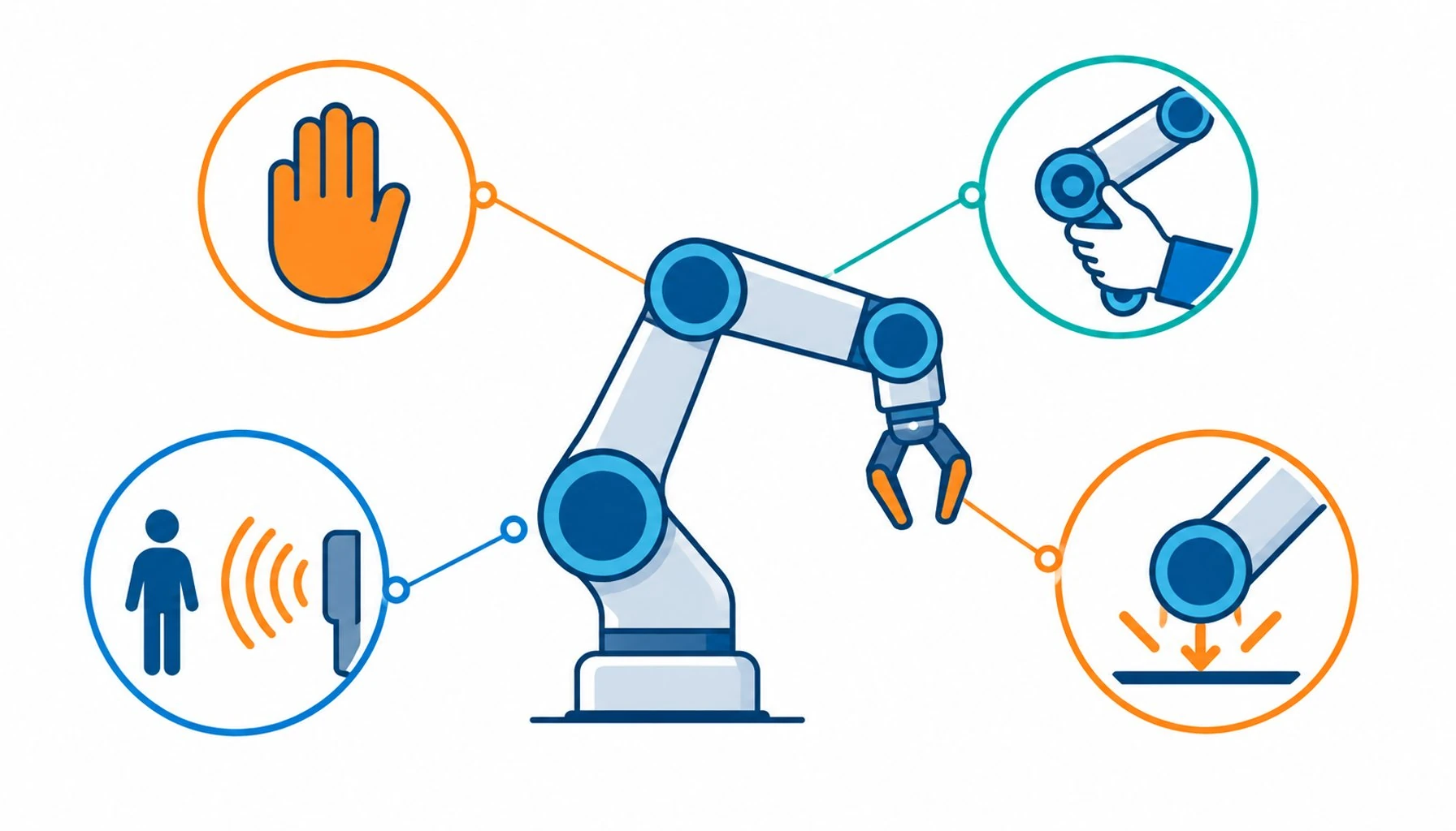
The document recognizes four ways for a robot and a person to share a workspace. Safety-rated monitored stop lets a person enter while the robot holds a supervised stop; the robot may resume when the person leaves. Hand guiding lets an operator move the robot directly through a guiding device, with the robot under speed and force supervision. Speed and separation monitoring keeps the robot moving but slows or stops it as the distance to the person shrinks, which depends on sensing that tracks where people actually are. Power and force limiting allows physical contact between robot and person, provided the forces and pressures at every foreseeable contact stay under the document’s biomechanical thresholds.
Each mode implies different hardware, and that is where the cable consequences begin. A stop-based mode leans on safety-rated sensing and stop circuits. A monitoring mode leans on continuous sensor data, which means signal cables carrying real-time measurements through a moving environment. A power and force limiting mode leans on the robot’s own control, but the application’s end effector, fixtures and surrounding cabling still share the workspace with the person, and their behavior under contact becomes part of the assessment.
| Mode | How it works | Typical applications | Cable-relevant demands |
|---|---|---|---|
| Safety-rated monitored stop | Robot holds a supervised stop while the person works inside the workspace | Machine tending, part loading at fixed stations | Reliable stop circuits and sensing feedback; harnesses that survive frequent stop-start duty |
| Hand guiding | Operator moves the robot through a guiding device under supervision | Positioning, teaching, small-batch handling | Continuous signal integrity through the guided device; cable dress that follows arm motion |
| Speed and separation monitoring | Robot adapts speed to the measured distance between itself and the person | Shared floor space, mixed traffic cells | Sensor signal cables rated for constant motion; separation between sensing and power circuits |
| Power and force limiting | Contact permitted, forces and pressures held under biomechanical thresholds | Close assembly, inspection, finishing beside operators | End-effector and fixture wiring assessed for contact; abrasion and crush resistance in shared space |
The Biomechanical Limits: What Contact Is Allowed to Feel Like
The most cited part of the document is its annex of biomechanical limit values: quasi-static and transient force and pressure thresholds for contact with specific body regions, from forearms to fingers to the skull. The integrator’s obligation is not to memorize the table but to use it: identify every plausible contact scenario in the application, calculate or measure the forces the robot and its payload would transfer in each, and demonstrate the values stay under the thresholds for the body region involved. Payload matters here in a way buyers often miss, because the same arm that passes with a gripper can fail the same assessment with a sharp fixture attached. The assessment covers the whole contact surface, tooling included, and the wiring attached to a moving end effector is part of that surface’s behavior.
It is worth stating plainly what the limits are for: they make contact survivable and pain-bounded, not pleasant. Applications that rely on frequent contact with a person’s face or other high-sensitivity regions usually fail assessment on practicality alone, and most successful power and force limiting applications are designed so contact is rare, incidental and on tolerant body regions.
Verification: How a Collaborative Application Proves Itself
The document expects the application’s claims to be tested, and verification practice has settled into a recognizable sequence: confirm the operating mode analysis against the as-built cell, measure or validate forces and pressures for the contact scenarios, exercise the sensing and stop functions through their full circuits, and record the results against the risk assessment. Verification that stops at the logic layer, the controller said stop, therefore the cell is safe, does not satisfy the intent, because a stop function that fails through a chafed cable or an intermittent shield is not a stop function. The failure modes that interrupt signal and safety circuits in moving machinery are cataloged in the guide to common cable failure causes, and verification through the wiring is the practical answer to them.
The verification steps, what each measures and what a pass looks like, are summarized below.
| Step | What is measured or checked | Pass condition |
|---|---|---|
| Mode confirmation | As-built cell matches the declared operating mode and its assumptions | No deviations between assessment and installation |
| Force and pressure validation | Contact scenarios measured or calculated against biomechanical thresholds | All scenarios under the limits for the body regions involved |
| Sensing function test | Sensors exercised through wiring and logic, including fault insertion where applicable | Functions available and correct through the full circuit |
| Stop function test | Stops initiated and measured at the robot, not only at the controller | Stops within specified performance through the wiring |
| Documentation review | Assessment, mode analysis, measurements and records assembled coherently | Evidence traces from findings to measures without gaps |
Where Collaborative Applications Stress Cabling Most
Three stress patterns recur in collaborative cells. First, shared space: cables routed where people reach are exposed to contact, snagging and abrasion, so jacket selection and routing discipline matter as much as in any guarded cell, with the difference that nobody expects a person to be there. Second, constant adaptation: monitoring modes keep the robot moving at varying speeds through long shifts, and the harnesses on the arm accumulate cycles steadily, which makes flex construction and bend radius discipline the durable part of the design. Third, sensing density: monitoring modes live on sensor data, and sensor cables run close to drive power in the same dress pack, so separation and shield planning decide whether the data stays clean. The cabinet-side arrangements that support clean signal routing are treated in the guide to control cabinet construction.
Buyers comparing suppliers for collaborative cells should also weight documentation heavily, because the verification file references component behavior: test data, material declarations and construction records feed the assessment directly. The reading discipline for those documents is covered in the guide to reading equipment datasheets.
When a Collaborative Approach Is Not the Answer
Honest limits: fenceless does not automatically mean cheaper or safer, and collaborative modes are a poor fit for some applications. High-payload processes, fast cycles with large swept volumes, and environments where sensing cannot reliably track people all tend to cost more to make collaborative than to guard conventionally. Applications with sharp tooling, hot surfaces or hazardous media bring contact risks the biomechanical framework was never meant to cover. And a collaborative design does not exempt the application from the machinery-level electrical obligations or from the certification layers export markets require, which are laid out in the equipment certification checklist. The honest decision sequence is to assess the application first and choose the mode second, not to start from the aesthetic of a fenceless floor.
RFQ Checklist: Specifying Cable for a Collaborative Cell
Attach these items to the cable portion of the RFQ:
- Operating mode and cycle profile: which mode the application uses, with expected motion rates per shift
- Contact exposure map: which cable routes sit inside human reach, with contact risk notes
- Sensing plan: which signal cables carry safety or monitoring data, with shield and separation requirements
- Motion envelope: bend radii, travel lengths and dress pack routing per axis
- Environmental envelope: temperature, coolants, swarf and cleaning regimes in the shared workspace
- Documentation package: flex test data and construction records that feed the verification file
Conclusion
ISO/TS 15066 turned fence removal from a bold claim into an assessable design discipline: four recognized operating modes, biomechanical limits that bound what contact may transfer, and verification that exercises the application through its real circuits. The requirements reward integrators who design sensing, routing and cabling as part of the safety case rather than after it, and they punish applications that borrow the collaborative label without the analysis behind it.
Kexingyu Cable Group (KXYE) supplies motion cable and harness support for collaborative and conventional cells alike, with the test documentation collaborative verification needs. Send your application’s cable scope through the RFQ page, and we will quote to the mode your cell actually runs.


