
The 800VDC Roadmap in Three Steps: What to Procure at Each Stage
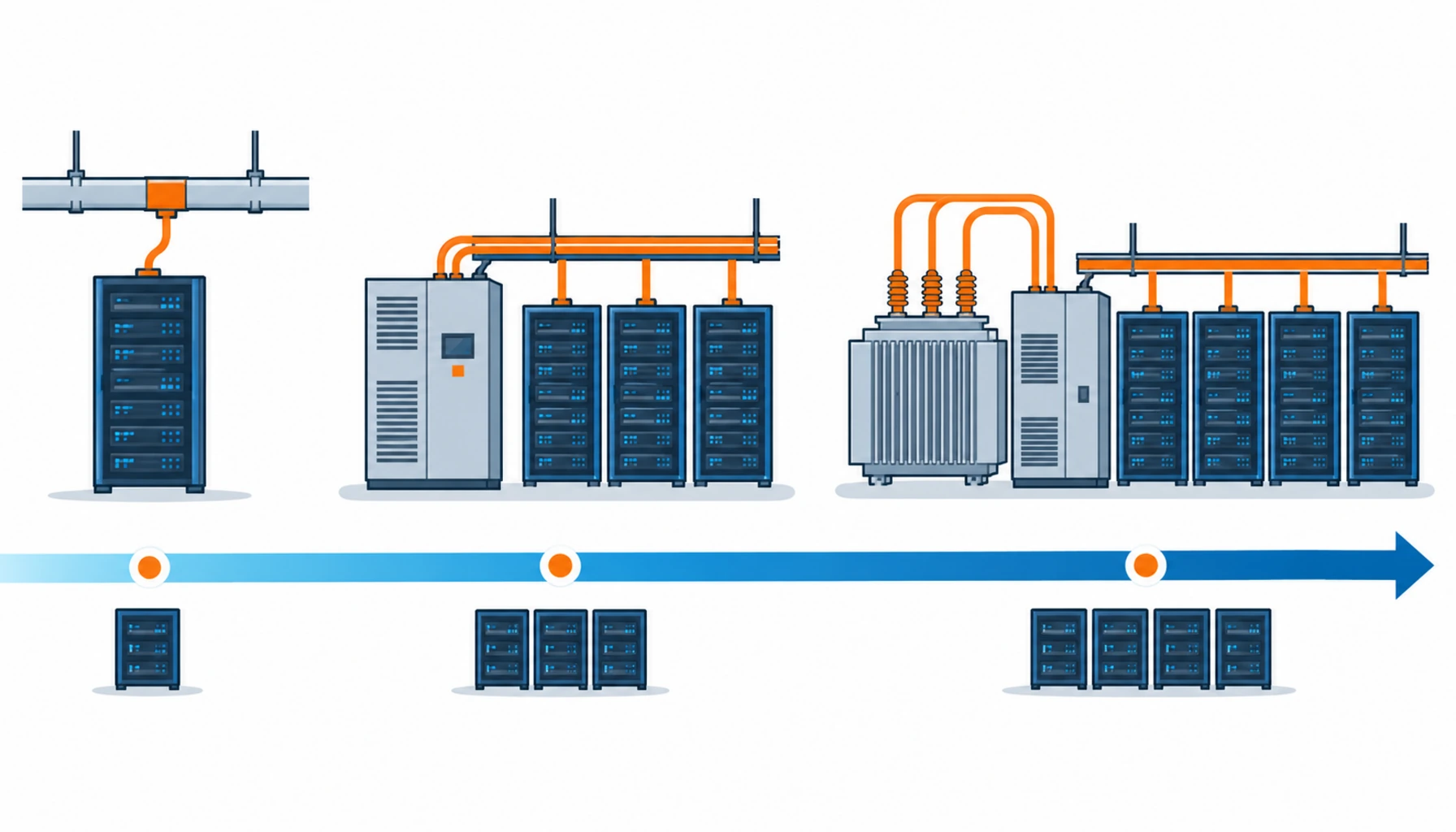
Quick Answer: NVIDIA’s 800VDC roadmap moves rectification from rack level in 2026 to cluster level in 2027 to room level by 2029, and each step changes what you buy, what certification you demand, and how far ahead you must place the order.
Most coverage of the 800VDC transition explains the architecture. That is not much use when you are the one holding the purchase order. The practical question is narrower and harder: at each step of the roadmap, what actually lands on your bill of materials, which items need a long lead time commitment now, and which parts of the specification you have to freeze before the design is finished.
Introduction
The roadmap published in NVIDIA’s 800VDC architecture whitepaper runs in three stages: rack-level rectification at roughly 660 kW in the third quarter of 2026, cluster-level centralised rectification at around 2 MW in the third quarter of 2027, and room-level distribution where medium voltage steps straight down to 800V DC through solid state transformers by 2029. Each stage solves the same copper problem in a different place.
What matters for procurement is that the three stages do not share a supplier list. The rack stage is a busway and connector problem. The cluster stage is a switchgear, rectifier enclosure and large-section DC cable problem. The room stage is a transformer and medium voltage problem. Buying against the wrong stage is how projects end up with equipment nobody can integrate. This article sets out what to purchase, what to fix in the specification, and where the traps sit — the architecture itself is covered in our companion piece on 800V DC data center power.
The Three Steps Compared on the Purchasing Side
The table below is the one to bring to a kick-off meeting. It maps each stage to the equipment categories it consumes and the point at which the order has to be placed.
| Stage | When | Where Rectification Sits | What You Buy | Order Lead Time |
|---|---|---|---|---|
| Rack level | From Q3 2026 | In a rack-side power shelf, roughly 660 kW per rack | DC busway and busbar tap-off, DC-rated breakers, busbar and cable connections, rack-level DC-DC converters | Busway and cable 6–10 weeks; DC breakers longer and short-listed early |
| Cluster level | From Q3 2027 | Centralised rectifier serving a cluster, around 2 MW | Medium voltage switchgear, rectifier enclosures, heavy-section DC cable, DC protection and isolation, cable tray and support | Switchgear 20–40 weeks; heavy DC cable 8–14 weeks |
| Room level | Toward 2029 | Medium voltage steps directly to 800V DC in solid state transformers | Solid state transformers, MV cable and terminations, room-level DC distribution, protection coordination study | SST supply is the pacing item; MV cable and terminations 10–16 weeks |
Step One: Rack Level, and What to Short-List Now
At the rack stage the rectification moves out of the server power supply and into a rack-side shelf, which means the distribution path between that shelf and the rack stops being a low voltage DC problem and becomes an 800V class problem. The items that change are the ones that touch the current: busway runs and tap-off boxes, the connection hardware at each tap, and DC-rated protective devices.
The purchase decision here is not which brand of busway to select. It is which current rating and which fault level to specify, because that is what determines whether the hardware is a catalogue item or a custom build. A rack busway ordered against a nominal current with no fault level nominated will come back with an unverifiable short-circuit withstand, and that becomes a commissioning argument later. Ask for temperature rise data at the rated current on the actual assembly, not a type test certificate on a similar one.
This is also where the practical gap sits. DC-rated breakers at these currents come from a small number of suppliers and their lead times run well past the busway. Placing the breaker order after the busway order is a routine mistake that adds weeks to a schedule for no reason. The busbar and tap-off hardware in a conventional distribution cabinet is a known product — our busbar tap-off box range is built on the same principle — but the DC rating is what has to be confirmed in writing before the order is released.
Step Two: Cluster Level, and the Switchgear Problem
At cluster level the rectifiers consolidate into a centralised plant serving around 2 MW, and the electrical centre of gravity moves to the medium voltage side. Procurement shifts to medium voltage switchgear, rectifier enclosures, and the heavy-section DC cable that carries the consolidated current from the rectifier plant out to the rack rows.
This is the stage with the worst lead time exposure. Medium voltage switchgear was already the bottleneck in 2026 before any 800V programme started, and the reasons are covered in our note on why switchgear and transformer lead times broke down. Adding a new generation of DC-rated equipment on top of an already constrained MV supply chain means switchgear has to be short-listed at concept stage, not at detailed design. If your project energizes in 2027, the switchgear enquiry is a 2026 activity.
The cable side is more tractable but has its own trap. Consolidated current at 2 MW is high enough that conductor cross-section and joint design become the defining specification, and the joint is where these installations fail first. Nominate the termination method, the torque specification and the inspection record in the enquiry rather than leaving it to site practice. Medium voltage switchgear and the transformers behind it are the product lines we build as standard — the KYN28 medium voltage switchgear enclosure is the conventional reference point — so the specification conversation can be had against real type-tested hardware rather than a datasheet promise.
Step Three: Room Level, and Why the Transformer Sets Your Schedule
The final stage removes the separate rectifier step altogether. Medium voltage steps down directly to 800V DC in a solid state transformer, which means the room-level distribution equipment and the transformer become one procurement package instead of two. The market for these devices is small but growing fast: published figures put solid state transformers at roughly USD 169 million in 2024 rising toward USD 936 million by 2030, a compound annual growth rate near 32 percent.
For a buyer, a young market means two things. First, the number of qualified suppliers is small enough that single-sourcing risk is real, and a second-source qualification should start before the first unit ships rather than after. Second, the protection coordination study is not optional — a solid state transformer changes the fault current characteristics that the downstream DC protection was designed around, so the study has to be commissioned with the transformer, not bolted on during commissioning.
One timing note that saves money: the roadmap is a vendor timetable, not a rule. Published penetration estimates put 800V at roughly 10 percent of the market in the near term, with AC UPS still holding more than 80 percent for the next three to five years. A facility that energizes in 2027 at moderate density is not obliged to buy step three hardware. What it should do is rate the distribution layer for the voltage it will eventually run, so the later move is a rack-level swap rather than a distribution rebuild.
What Each Step Changes in Your Cable and Busway Schedule
Across all three stages the same specification items move, and they move at different times. The table below is the checklist version — the items to fix in the specification at each stage, and what goes wrong when they are left open.
| Specification Item | Rack Level | Cluster Level | Room Level | Error It Prevents |
|---|---|---|---|---|
| Voltage rating of the distribution layer | 800V DC class, even if energizing lower | 800V DC class with MV feed rated for final build | MV and DC sides rated together | A rack-level change turning into a full distribution rebuild |
| Fault level and short-circuit withstand | Declared at each tap-off point | Coordinated across rectifier plant and rows | Re-studied for solid state transformer characteristics | Unverifiable withstand figures and commissioning disputes |
| Termination and joint method | Tap-off connection hardware specified by type | Heavy-section DC joint method, torque and inspection records | MV termination kits and installer qualification | Site-practice joints that fail thermally within the warranty period |
| Route and support | Tray fill and grouping for the rack row | Tray, support and fire-stop for consolidated runs | Room-level routing and clearance | Derating assumptions that do not survive the installed layout |
| Documentation and test evidence | Temperature rise at rated current on the actual assembly | Conductor resistance and batch records, witness testing | Type test and coordination study reports | Accepting a general certificate in place of construction-specific evidence |
When the Three-Step Roadmap Is Not Your Purchase Plan
The roadmap is written for AI training halls heading toward a megawatt per rack. Applied to the wrong project it creates cost with no return. Three conditions mean you should not buy against it.
Density below roughly 100 kW per rack. Conventional AC distribution with in-rack conversion remains cheaper to build and to staff, the equipment is available from many sources with short lead times, and no new training or DC-rated test gear is needed. The example of the older architecture is set out in our note on 415V data center distribution — for general-purpose compute that design is still the correct purchase.
A project energizing before the supply chain is ready. Committing to DC-rated protection and connectors before a competitive second source exists turns a specification choice into a single-source dependency, and it is not recoverable once the design is frozen. The realistic middle path most operators take is to rate the layer high and energize low — a purchase decision that costs little now and preserves the option later.
No engineering depth to run protection coordination. Fault energy and protection coordination both get harder as voltage rises. A site without the capability to design and verify those systems is better served by proven architecture than by an ambitious one, and the failure mode is not a slower schedule but an installation that cannot be signed off.
The common procurement error across all three is buying the roadmap instead of the requirement. A power shelf, a rectifier plant and a solid state transformer are not interchangeable line items, and a specification written around the stage rather than the load will produce a bill of materials that matches a whitepaper and not a building.
RFQ Checklist: What to Send With Each Enquiry
Send the electrical consequences, not just the power figure. Each enquiry should carry:
- Rack power per row and per hall, with the density profile across fit-out phases
- The roadmap stage being purchased against, and the final voltage the layer must be rated for
- Current per feed and the fault level expected at each distribution point
- Whether the layer is energizing below its rating, and the plan for the later migration
- Route conditions: tray fill, grouping, ambient temperature, vertical rises and fire-stop requirements
- Distribution voltage class and the DC rating evidence required for breakers and connection hardware
- Termination and joint responsibility, with the torque values and inspection records you will accept
- Test documentation: temperature rise at rated current on the actual assembly, conductor resistance, batch traceability
- Certification for the destination market, and the edition of each standard the equipment must meet
- Second-source and spare-parts position for long lead items, stated as a delivery commitment rather than an intention
Conclusion
The three-step roadmap is a buying sequence before it is an engineering story. Rack level is busway, tap-off and DC protection; cluster level is switchgear, rectifier enclosures and heavy DC cable; room level is the solid state transformer and the MV package around it. The stages use different suppliers, carry different lead times, and fail for different reasons — which is why the specification has to be written stage by stage rather than as one electrical scope.
Two decisions carry most of the cost. Fix the voltage rating of the distribution layer at the final figure even if you energize lower, so the migration stays at rack level. And place the long lead items — switchgear and DC protection first, transformers next — against the final build rather than the current phase, because the supply chain, not the physics, is what usually decides the schedule. Kexingyu Cable Group (KXYE) supplies the power, control and mineral insulated cable ranges used in these facilities — WDZ-YJY, WDZN-YJY, BTTZ, BBTRZ, NG-A (BTLY), KVV and YJV — together with medium voltage switchgear and transformer product lines, from a single factory group, with copper price linkage available on project-scale orders. Send your rack power target, route conditions and final voltage and we will size the schedule; the fastest start is a request for quotation, or browse the transformer and substation range at transformers and substations.


