Fire Alarm and Emergency Lighting Circuits: Cable to Specify
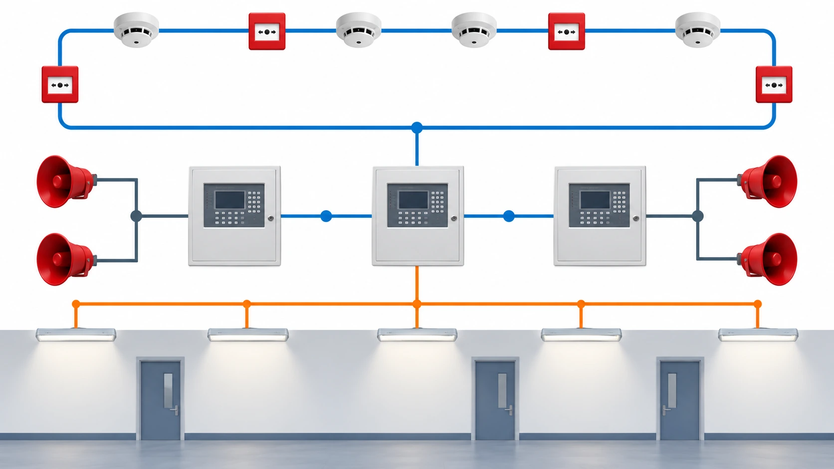
Quick Answer: These circuits are not bought for current, they are bought for two other things: whether the circuit keeps working long enough for people to leave, and whether the signal on it stays clean enough to be trusted. Detection loops and emergency lighting supplies have different requirements that are often specified as one item. Separate them, set the integrity duration and the screening arrangement for each, and buy the cable with the terminations its approval names.
Introduction
Fire alarm and emergency lighting circuits are the cheapest cable on a building project and the ones most likely to cause a commission to fail. The reason is not cost, it is that they are usually specified in a single line by somebody who has the fire strategy in front of them and the equipment schedule somewhere else. A detection loop, a sounder circuit, a network backbone and an emergency lighting final circuit have four different jobs, and only one of them is about carrying power.
This guide separates the duties, sets out what each one needs specified and evidenced, and lists what to freeze so the circuits arrive consistent with the panel and the luminaires they serve.
Two Families of Circuit, Two Different Questions
The alarm side is a signalling problem. Detection loops carry small currents with data superimposed, and the question is whether the signal survives physical damage, screening faults and the fire itself. Conductor size is almost irrelevant; screening, pairing, topology and integrity are everything.
The emergency lighting side is partly a power problem and partly a signalling one. The supply to the luminaires has to hold up for the escape duration, and the final circuit has to deliver enough voltage at the far end for the luminaire to reach its required output. Here conductor size does matter, and it is the calculation most often skipped.
Both sit under the same fire strategy and both are commonly bought with a fire-rated label attached to whichever construction was cheapest. The two questions they answer are different enough that a single line on the schedule is the wrong way to buy them.
The Alarm Side: Integrity, Screening and Topology
Circuit integrity. The alarm has to keep signalling while the building is being evacuated, which means surviving the fire for a stated duration in the part of the building where the fire is. The requirement is normally expressed as an integrity grade and duration for the circuit, tested while energised, and it applies to the whole circuit and not to the cable alone.
Screening and pairing. A detection loop is a data circuit, and a data circuit in a building shares its route with power. Screened twisted pairs are the normal answer, with the screen earthed at the end and in the manner the panel manufacturer requires, because an earth loop through a screen causes faults that appear and disappear with the load. The constructions available for this duty, including the paired and screened families, are set out in the multi-pair screened range.
Topology and length. Loop, spur and star topologies each have a length limit set by the panel and the protocol, and those limits are electrical facts rather than guidelines. A loop that exceeds them works in the factory and fails on site, and on a long site the limit is reached earlier than anybody expects. Where the length is the constraint, the answer is usually more panels or a different topology rather than a thicker cable.
The backbone. Where alarm panels talk to each other across a campus or a tall building, the network cable is its own specification with its own integrity requirement. Treat it as a separate line on the schedule, because it is frequently forgotten until the panels are installed. The data-cable side of the family sits alongside the alarm and signal cable range.
Circuit Types and What Each One Needs
| Circuit | Duty | What to Specify | Evidence to Demand | Cost and Lead-Time Driver | How It Fails |
|---|---|---|---|---|---|
| Addressable detection loop | Small current with data, must survive damage and the fire locally | Integrity grade and duration, screened twisted pairs, screen earthing convention, pair count and spare capacity | Integrity test evidence, screen continuity records, panel compatibility and protocol length limits | Certified construction and screening drive cost; the pair count is set by the device schedule | Signal loss where the loop is fire-damaged, screen earth loops causing intermittent faults |
| Conventional zone and sounder circuits | Power to sounders and beacons, voltage sensitive at the end of the run | Conductor size for volt drop at the last device, integrity grade, circuit protection and cabling topology | Integrity test evidence, voltage drop calculation, sounder load schedule | Copper is small; the grade and the topology drive the order | Sounders that are quiet at the far end because the voltage drop was never calculated |
| Alarm network backbone | Panel-to-panel communication through the building or campus | Integrity grade, protocol and cable type, screen and earthing, distance limits between nodes | Integrity test evidence, protocol compatibility statement, screen continuity records | Specialist data construction with limited suppliers; lead time follows the tested build | Panels that lose contact under fire or interference, distance limits exceeded between nodes |
| Emergency lighting supply | Hold the luminaires at output for the full escape duration | Integrity grade and duration, conductor size for voltage drop at the last luminaire, route inside protected construction | Integrity and smoke test evidence, voltage drop calculation for the final circuit, commissioning records | The integrity grade rather than copper drives cost, but the volt drop can force a larger size | Luminaires that dim below the required output because the final circuit was undersized |
| Emergency lighting monitoring | Self-test and status signalling back to the control system | Integrity requirement on the monitoring path, screen and earthing, addressing and spare capacity | Integrity test evidence where required, compatibility with the monitoring system | Small conductors; the system compatibility is the constraint rather than the cable | Luminaires that light correctly but cannot be tested or reported, failing the maintenance regime |
The Emergency Lighting Side: Duration and Voltage Drop
Emergency lighting is judged on whether the luminaire produces enough light for long enough, and two procurement mistakes sit either side of that sentence.
Duration is a circuit property. The escape strategy sets how long the lighting must work, and the circuit has to keep supplying the luminaires for that period under fire conditions. The integrity grade and duration belong on the cable schedule, tested on the installed assembly. Where the luminaires themselves have a battery, the cable’s job is to keep charging and signalling, which is a different requirement from supplying them during the incident, and the two must not be confused on the schedule.
Voltage drop is where the failure usually is. Small lighting loads make it tempting to cable the final circuit to the breaker rating rather than the load, and the last luminaire on a long run then receives less voltage than it needs to reach its rated output. The calculation is arithmetic and it belongs in the order, not at commissioning. Our note on the fire rated control and power range covers the constructions used for this duty.
Route and protection. An integrity grade is a claim about the installed circuit, so the route, the fixings and the penetration details are part of the purchase in the same way they are for a fire pump supply. Our note on fire survival grades covers how the duration and the test conditions differ between schemes.
Where These Circuits Share a Route with Power
Alarm and emergency lighting circuits rarely get a route of their own. They share ceiling voids, risers and service corridors with power, and that is where most of the practical problems come from.
Separation and segregation. Screened data pairs run alongside motor feeders, drive output cables and lighting circuits that switch hard. The separation the installation standard requires is the baseline; where the route is tight, a screened construction with proper earthing is the practical answer rather than a wider tray that the ceiling cannot take. The screened and armoured instrumentation families used for this, including the screened instrumentation constructions, are chosen for the screen and the drain arrangement rather than the conductor.
Parallel routes and compartment crossings. Where alarm and power cables cross a slab together, the penetration detail has to suit both, and a detail tested for one construction does not automatically cover the tray full of mixed types. Our note on firestop cable penetrations covers what the detail must include, and the mixed tray is the case most often handled with a generic sealant detail that fails inspection.
Earthing and bonding. Screens, armour and containment all end up bonded somewhere, and the arrangement has to be consistent across the circuits that share a route. Getting it wrong produces the intermittent faults that appear when a drive starts, and they are the most expensive faults to trace on a completed building.
Handover records. Separation, screen earthing and penetration details are all things a commissioning engineer checks and a maintenance electrician will need later. Record them with the circuit tests rather than leaving them as a site practice that only the original crew knew.
What to Freeze Before the Order
| Decision | What to State | Evidence to Attach | Cost of Leaving It Open |
|---|---|---|---|
| Duty per circuit | Detection, sounder, backbone, supply or monitoring, circuit by circuit | A circuit schedule mapping duties to the panel and luminaire schedules | One construction bought for five different jobs |
| Integrity grade | Duration and test conditions for each circuit that must survive | Integrity test report plus the system approval for terminations and fixings | A circuit that signals correctly in a test and fails in a fire |
| Screening and earthing | Screen type, pair arrangement and the earthing convention the panel requires | Panel manufacturer's installation requirement, screen continuity records | Intermittent faults that are traced to an earth loop months later |
| Voltage drop | Luminaire and sounder loads, with the voltage required at the last device | The calculation and the conductor size it produces | Sounders that are quiet and luminaires that are dim at the far end |
| Topology and limits | Loop, spur or star, with the distance limits per circuit | Panel or protocol documentation with the limits marked | A circuit that works on the drawing and not on the site |
| Spare capacity | Spare pairs and spare devices allowed per circuit | The device schedule with the spare allowance stated | Re-cabling a completed floor when the fit-out changes |
Evidence at Commissioning
Loop continuity and resistance. Every loop measured end to end, with records, because a high-resistance joint in a detection loop shows up as partial device loss rather than a clean failure.
Screen integrity. Continuity and insulation checks on the screens, with the earthing convention confirmed against the panel manufacturer’s requirement. Our note on insulation resistance testing covers the measurements, and on a screened data circuit they are worth doing before the panel is commissioned rather than after.
Functional test under load. Sounders at the last device, luminaires at the end of the longest final circuit, and the monitoring path reporting correctly. These are the three tests that find the sizing and compatibility mistakes, and all three are cheap before handover and expensive afterwards.
When a Fire Alarm Cable Specification Is Not the Answer
When the panel is the constraint. If the protocol has a distance limit, no cable changes it. Add a panel, change the topology or move the node, rather than buying a higher grade of the same construction.
When the fault is screening practice. Intermittent alarms on a loop with screened cable are usually earthed at both ends or bonded in several places. The construction is fine; the termination is not.
When the luminaires are the problem. A luminaire that cannot reach its output on the available voltage, or that is not compatible with the monitoring system, is a luminaire problem and no cable solves it.
When the route is unprotected. An integrity grade assumes a route and a fixing detail. If the circuit crosses unprotected space, the answer is the route, not the class.
RFQ Checklist
- Circuit schedule separating detection, sounder, backbone, supply and monitoring duties
- Integrity grade and duration for every circuit that must survive a fire
- Screening arrangement and the earthing convention the panel requires
- Panel or protocol distance limits applied to each circuit and topology
- Voltage drop calculation for sounder and emergency lighting final circuits
- Conductor sizes with spare pairs and spare device capacity allowed
- Termination and fixing system as part of the approved assembly
- Route drawing with protected sections and firestop details marked
- Tests to be witnessed and the records that ship with each drum
- Compatibility statement for the panel, the luminaires and the monitoring system
Conclusion
Fire alarm and emergency lighting cable is bought on two questions, and neither is about current. Does the circuit keep working long enough, and does the signal stay clean enough to be trusted. Answer both per circuit, put the integrity grade, the screening arrangement and the voltage drop calculation on the schedule, and buy the terminations the approval names. The cable is cheap either way; the commissioning failure is not.
Kexingyu Cable Group (KXYE) has manufactured cable in Quanzhou since 1996, supplying the paired, screened, fire-rated and control constructions that alarm and emergency lighting circuits need, with the test records and terminations their approvals depend on. Send us the circuit schedule with the panel and luminaire details, the integrity durations and the route conditions, and we will come back with the constructions and the evidence that applies to each. The fastest route is a request for quotation.