
Abrasion and Chip Resistance: Jacket Tests That Actually Matter on Machines
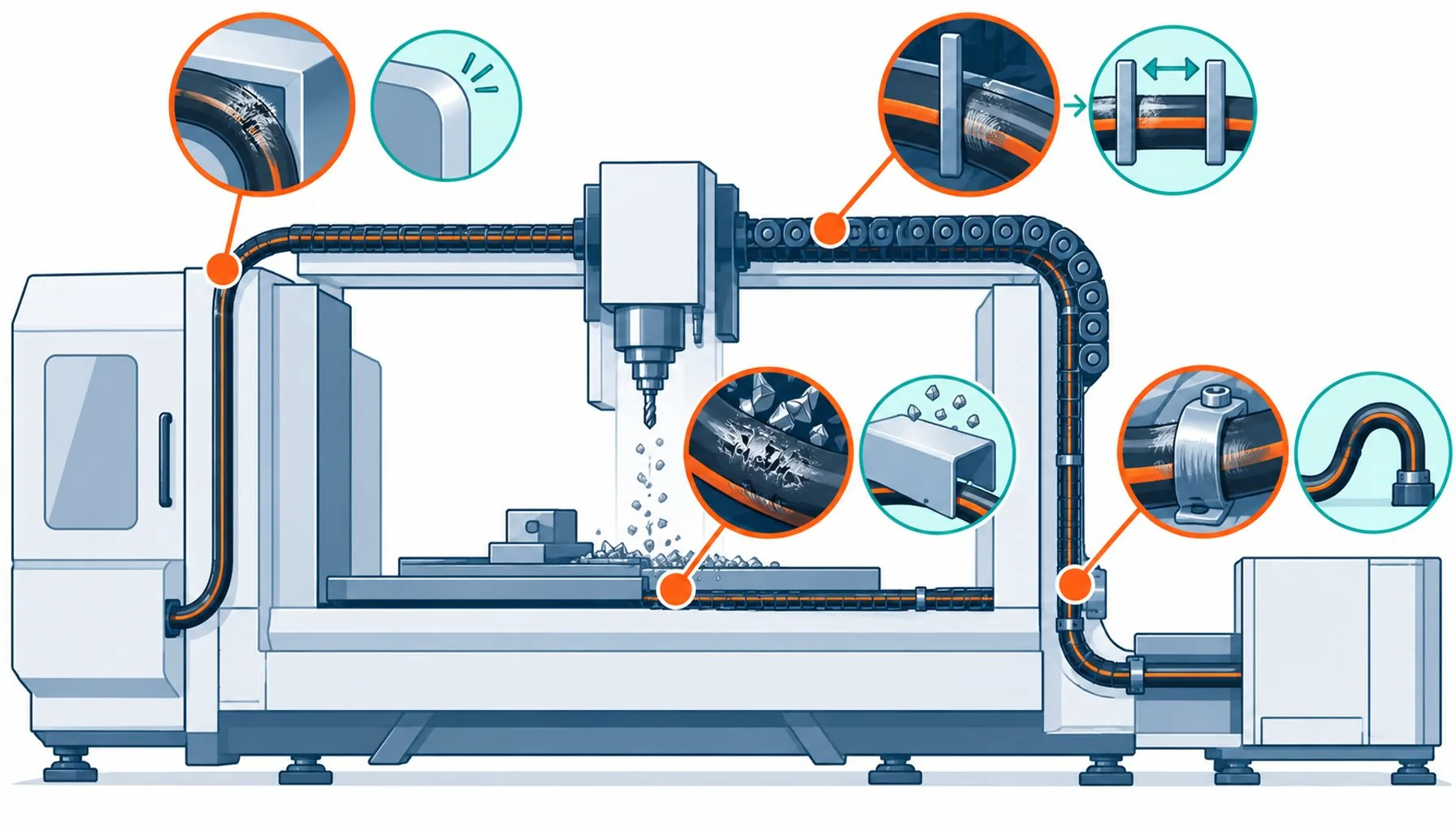
Quick Answer: Most jacket wear on machines comes from rubbing and chip strike at a few predictable contact points; abrasion-resistant compounds help, but routing that removes the contact removes the failure entirely.
Every maintenance engineer can point to the same spots on the same machines: the cable that wears through at the frame edge it crosses every cycle, the jacket gone white and powdery where the chain divider rubs it, the slice where a stray chip landed during a roughing pass. Abrasion is the most preventable failure in machine cabling and still one of the most common, because it is treated as a materials problem when most of it is a geometry problem. This guide covers how jackets actually wear, which laboratory abrasion tests correspond to which real-world wear modes, what chip strike adds to the picture, and how to combine compound choice with routing discipline so the cable outlives the machine’s first major overhaul.
Introduction
A cable jacket exists to take the abuse the environment deals out, and on a machine tool or robot cell the abuse is mostly mechanical contact: rubbing against guides and dividers, sliding across frame edges, being struck by swarf, crushed by clamps, dragged across debris. Compound engineers answer with harder, slipperier, tougher jackets, and the good ones genuinely last longer. But the failure statistics of machine cabling keep repeating the same lesson: the wear concentrates at a handful of contact points, and those points are design decisions made before any cable was purchased.
The useful way through this subject is to treat wear as a system: a contact force, a surface, a motion and a material, repeating. Change any one and the wear rate changes; remove the contact and the wear stops. The sections below go through the wear modes, the tests, the compounds, and the routing practice that makes abrasion ratings almost a formality.
The Four Wear Modes on Real Machines
Sliding abrasion is the baseline: cable rubs a surface every cycle, the surface removes jacket material grain by grain, and the failure shows as a smooth wear flat that deepens until it threatens the braid. Edge contact concentrates it: the same rubbing but across a small radius edge, where contact pressure multiplies and the wear flat becomes a wear groove. Impact and chip strike add discrete events: sharp swarf at cutting speed slices or gouges the jacket, and a single deep gouge can end a cable that sliding wear would have taken years to touch. Crush and pinch damage masquerades as abrasion when the jacket finally wears through at the compressed point, though the root cause was a clamp or a door edge, not rubbing.
Each mode has a different defense. Sliding wear responds to compound hardness and low friction, and to separators that replace cable-on-cable contact with controlled sliding surfaces. Edge wear responds to routing: radiused edges, wear plates, clips that hold the cable off the corner. Chip strike responds to protection, which may be a tougher compound or, better, physical shielding and top-side routing. Crush responds to hardware discipline. A specification that only names a compound answers one of four modes.
What the Abrasion Tests Measure
Laboratory abrasion tests draw, rotate or reciprocate a sample against a defined surface under defined load and report cycles, weight loss or visual failure. They are excellent at comparing compounds: run two jackets through the same reciprocating test and the survivor ranking is real. They are weaker at predicting life, because the contact geometry of a test rig rarely matches the contact geometry of the machine: a flat slider does not behave like a frame edge, and neither behaves like a chain divider gliding under coolant.
The gap closes with application-relevant tests, and the best suppliers run them: chain tests with the cable riding actual dividers, reciprocating tests over a radiused edge rather than a flat plate, and cut-resistance tests for chip-exposed positions. When comparing jackets, the question to ask is not the abrasion number but the geometry behind it. A moderate result over a radiused edge predicts machine service better than a spectacular result on a flat slider.
Compounds: What Each Actually Buys
PUR dominates abrasion-critical cabling for good reason: the compound combines high abrasion resistance with the oil resistance machine tools demand, and its low friction lets cable slide over guides rather than dragging. TPE blends trade some abrasion for better cold behavior. PVC sits far down the ranking for continuous contact, though it survives occasional light rubbing in dry cabinet environments. Reinforced or fabric-braid-covered jackets occupy the extreme end, buying chip and cut resistance for positions where swarf is routine. None of these compounds saves a cable clamped against a moving edge; all of them last dramatically longer once the routing gives them a fair chance, and the pairing of compound and routing is where the specification earns its keep.
Routing Discipline: The Cheapest Abrasion Resistance
The highest-leverage abrasion decisions cost nothing. Hold cables off frame edges with clips and standoff brackets so contact never happens. Radius every edge the harness crosses, or add a wear plate where it cannot be avoided. Separate cables inside carriers with dividers so neighbors slide on controlled surfaces instead of each other. Route chip paths so swarf falls away from the harness, and shield the unavoidable positions. Keep cables below their own weight off surfaces with proper support spacing, and leave service loops slack enough that machine flex does not drag the jacket across fixtures. None of this appears on a datasheet, and all of it appears in the service life of the cable, which is why experienced machine builders treat harness routing as a design review subject with the same weight as component selection.
Against these stands the routing discipline, which costs nothing and outlasts every compound, and which the next section treats in detail. The compound decision itself compresses into the comparison below.
| Contact point | Wear mode | First defense (routing) | Second defense (material or hardware) |
|---|---|---|---|
| Frame edge crossed every cycle | Edge wear groove | Radius the edge or clip the cable clear of it | Wear plate; PUR compound at the contact |
| Chain divider contact | Sliding abrasion, continuous | Correct divider spacing per cable diameter | Low-friction PUR jacket rated for chain duty |
| Chip fall path | Chip strike, slicing | Route above the fall line; add deflector shields | Fabric-braid-covered or specialty jacket at unavoidable positions |
| Cable resting on wet debris surface | Sliding abrasion with chemical assist | Support spacing that lifts the cable off surfaces | Oil-and-abrasion-resistant compound per the fluid zoning |
| Door and clamp pinch lines | Crush presenting as wear | Re-route clear of pinch geometry entirely | Protective channel; the compound cannot fix a pinch point |
| Cable-on-cable inside bundles | Internal sliding wear | Bundle size limits and separators | Low-friction jackets; sleeve the hottest pair |
The Wear Audit: Finding the Points Before They Find You
Where wear cannot be routed away, armor becomes a legitimate option, and the trade-offs between protected and unprotected constructions are compared in the guide to armored versus unarmored cable, with the caveat that armor fixes strike and crush far better than it fixes continuous rubbing. The broader pattern of mechanical and environmental causes behind cable failures is catalogued in the standard review of common cable failure causes.
The hardware that holds the harness in place decides several of the contact points before the cable arrives. Clips, saddles, dividers and glands are the accessories layer of the specification, and the selection logic for them is treated in the guide to cable accessories selection. Where the harness crosses between machine and cabinet, the transition hardware and entry discipline belong to the wider cabinet layout, covered in the guide to control cabinet construction, and the plant-level context of protecting cable runs sits within the broader industrial power distribution checklist.
When Abrasion Ratings Are Not the Answer
The practical tool for existing machines is the wear audit: walk the harness with the machine running, note every point where cable touches anything, and grade each contact by motion, pressure and evidence of past wear. The table below turns the audit into a checklist with the standard defenses, and it doubles as a design-review template for new machines. Ten minutes with a flashlight prevents most of the abrasion failures a shop will otherwise meet.
| Compound | Abrasion rank | Chip and cut resistance | Other notes for the choice |
|---|---|---|---|
| PUR | Highest of the standard compounds | Moderate | Also carries oil resistance and low friction; the machine-tool default |
| TPE blends | Moderate to high | Moderate | Better cold flex; chosen where temperature range competes with wear |
| PVC | Low under continuous contact | Low | Dry, light-duty positions only; swells and extracts in oils |
| Fabric-braid covered | High, wear acts on the braid | Highest of the options | Chip-exposed and foundry-like positions; thicker, costlier |
| Fluoropolymer and specialty | Varies by formulation | Often high | Chosen for combined chemical and mechanical extremes |
RFQ Checklist: Specifying Abrasion Performance
Honest limits: an abrasion rating is a comparison tool, not a life prediction, and no compound outranks its routing. There are environments where wear is not the limiting mechanism at all, and overspecifying abrasion there wastes money the fluid, heat or flex specification needed; the jacket that resists chips best is sometimes poor at cold flex, and the trade must be made consciously. Extremely abrasive positions, foundry-like debris fields and continuous granular contact, exceed what any jacket tolerates bare, and the honest answer is conduit, armor or physical separation rather than a better polymer. And wear on a cable is sometimes the symptom of a deeper fault, a failing guide or a shifted fixture, in which case replacing the cable without fixing the machine guarantees the next failure. The rating belongs at the end of the specification, after the geometry has done its work.
Conclusion
Bring the wear to the supplier in specifics:
- Contact map: where the harness touches machine surfaces, and what moves at each contact
- Wear mode per contact: sliding, edge, chip strike, crush, identified from the audit
- Environment at each point: fluids, temperature, debris type and size
- Evidence required: abrasion test geometry matching the real contact, chain-divider data for carrier positions
- Compound per zone, with the trade-offs stated if chip and cold duties conflict
- Routing review: supplier feedback on the harness layout before the cable is built


