
Cable Derating Factors: Temperature, Grouping and Installation Method
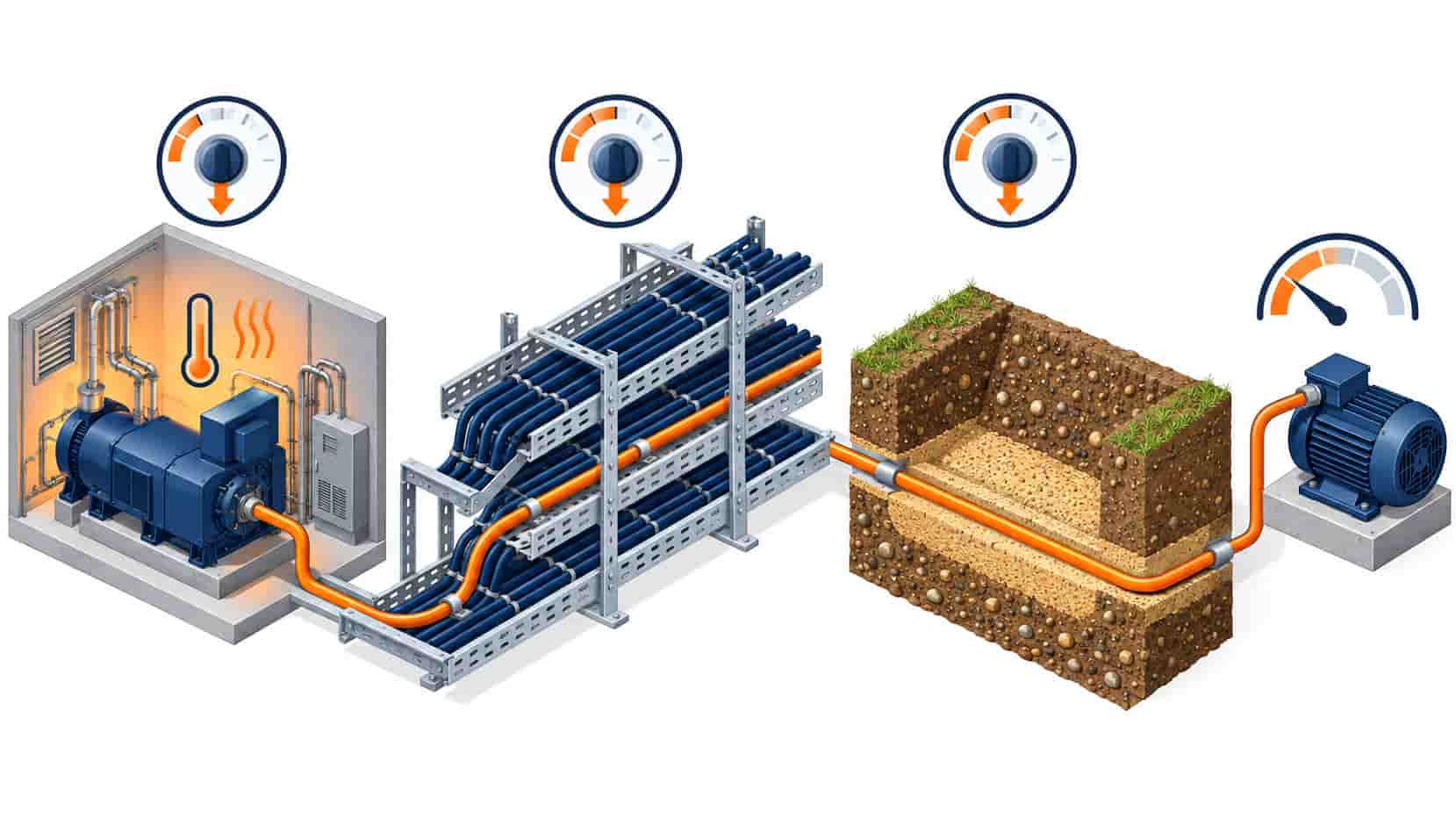
Quick Answer: Published ampacity assumes standard conditions; real installations multiply it down — ambient, grouping, soil and depth cut the rating, grouped buried circuits commonly losing 30-60 percent. The most expensive number in cable procurement is the one printed in the catalogue, because it's almost never the number the installation delivers. Ampacity tables assume a reference world — standard air temperature, one cable, standard soil — and every deviation from that world multiplies the rating down. A feeder that passes the datasheet check and fails the derating check is a classic procurement failure: discovered not at the factory but in the first summer, as a warm trench and a tripping breaker. This guide walks the four factor families, shows how they multiply, and points at where the losses concentrate.
Introduction
A cable’s current rating is a thermal equilibrium statement: the conductor reaches its maximum permitted temperature when the heat it generates equals the heat the surroundings carry away. The catalogue number fixes the generation side with standard conditions and assumes a reference environment on the other side. Real installations differ from that environment in four systematic ways — the air or soil is hotter, the cables are not alone, the soil conducts heat worse than assumed, and the burial is deeper than the reference — and each difference has a correction factor published in the rating standards. The correction logic is simple multiplication. The discipline is refusing to skip it. The base sizing arithmetic that the corrections multiply is worked through in our cable size selection guide, and this guide covers what multiplies it.
Factor One: Ambient Temperature
The first correction is the environment’s temperature against the reference. Air-rated tables assume 25°C, 30°C or 40°C depending on the standard, and buried tables assume a soil temperature — typically 15°C to 25°C — at the reference depth. A cable in a plant room that reaches 45°C in summer, a rooftop run in a Gulf summer, or a duct bank in warm soil all need the temperature factor applied: the factor falls as ambient rises, and for XLPE insulation with its 90°C conductor limit the correction is gentler than for PVC’s 70°C, but it is never free. The trap is seasonal. A schedule checked against annual average temperatures passes on paper and overheats in the two weeks a year that matter. Use the worst credible sustained temperature — the design summer maximum for air, the measured summer soil temperature at depth for buried runs — and the factor protects the installation the weather actually delivers.
| Factor | Reference Assumption | Typical Correction Range | Where It Bites Hardest |
|---|---|---|---|
| Ambient temperature | 25-40°C air or 15-25°C soil by standard | 0.80-1.05 | Plant rooms, rooftops, hot-climate buried runs |
| Grouping | Single circuit alone | 0.50-0.90 for touching groups | Tray layers, trench formations, duct banks |
| Soil thermal resistivity | Standard soil (â1.0-1.2 K·m/W) | 0.70-1.00 | Dry sand, backfill with poor compaction |
| Depth and formation | Reference depth, single row | 0.85-0.95 per extra variable | Deep duct banks, multi-row formations |
Factor Two: Grouping — The Largest Loss
Cables heat their neighbors, and grouped circuits share the thermal burden: each additional touching circuit raises the temperature of the group, so every member’s permissible current falls. The grouping factor is the steepest of the corrections — a touching horizontal group of four to six circuits can lose a third of its individual rating, and multi-layer tray installations lose more. Data halls and industrial cable rooms concentrate exactly this geometry, which is why their power-dense tray fields need the grouping arithmetic done section by section rather than as a single average — the density profile behind those fields is covered in our data center power guide. The engineering countermeasures are spatial: spacing between circuits, vertical separation on trays, single-row formations in trenches, and where the design forces density, upsizing the conductor to carry the corrected load. The worst outcome is quiet — a tray filled to the drawing’s cable count but beyond its thermal count, passing every inspection and running hot for its whole life.
Factor Three and Four: Soil, Depth and Formation
Buried circuits inherit the soil’s thermal character. The reference tables assume a standard thermal resistivity — the soil’s ability to carry heat away — but real backfills vary enormously: dry sandy soil insulates rather than conducts, poorly compacted backfill dries out around a hot cable and worsens its own resistivity in a self-reinforcing loop, and the duct bank’s concrete changes the geometry entirely. Depth adds its own correction, and multi-row or multi-duct formations stack grouping effects on top. The honest method measures or specifies the actual backfill — thermal-resistivity-tested engineered backfill is a standard line item in serious buried projects — and runs the corrections for the true depth and formation rather than the table’s default. Where the route passes through mixed soils, the worst section governs, because the cable’s heat travels through every meter of its length equally. The hot spot, not the average, sets the rating. The failures that careless thermal design seeds — chronic hot spots and accelerated insulation aging — are the thermal entries in our cable failure causes guide.
Running the Corrections Honestly
The corrections multiply: a 0.88 temperature factor, a 0.65 grouping factor and a 0.85 soil factor compound to roughly half the catalogue number, and the feeder sized without them is half a feeder. Three disciplines keep the arithmetic honest. First, use one consistent standard set for the base table and its factors — mixing an IEC base with national factors produces fiction. Second, correct at the worst section: the hottest room, the densest tray tier, the driest soil stretch each apply their factor to the circuits they touch, and the circuit’s rating is the minimum across its route. Third, document the factors in the schedule itself, because the installer who adds one circuit to a sized tray must see the grouping factor that breaks — the documentation habit that keeps ampacity decisions auditable is the same report-verification discipline applied to factory claims in our power cable manufacturer checklist. And where the calculation is contested or the installation unusual, the rating standards’ calculation frameworks — IEC 60287 and its national analogues — formalize it; the standards landscape around them is mapped in our MV and LV standards guide.
| Input | Where It Comes From | Common Error |
|---|---|---|
| Design air temperature | Site climate data, room heat load worst case | Using annual average instead of summer max |
| Grouping count | Tray drawings, worst tier, final fill | Sizing on installed count, ignoring future circuits |
| Soil resistivity | Measurement or engineered backfill spec | Assuming table default in dry or sandy ground |
| Depth and formation | Trench section drawings | Ignoring multi-row stacking effects |
| Governing section | Route walk, worst segment identified | One factor set applied to the whole route |
When Derating Tables Are Not the Answer
The factor tables are correlations from standard geometries, and several situations outrun them. Cyclic loads — feeders that run hard for hours then rest — can legitimately exceed the steady-state table, but exploiting the cycle needs the cyclic-rating calculation, not a guess. Very deep banks, unusual backfills and dense duct arrays need the full calculation framework rather than the factor tables. Cables in enclosed troughs with no air movement sit outside the free-air assumptions entirely. And mixed installations — part tray, part buried, part duct — govern from their worst section, which the single-factor habit misses. In all of these, the response is the calculation, not a fudged factor. The tables are the fast path for ordinary cases, and knowing the boundary between ordinary and extraordinary is part of the sizing competence.
RFQ Checklist: Making Ampacity Verifiable
Make the rating chain auditable, so include:
- Design ambient stated per route section: air max, soil temperature at depth
- Grouping described: circuits per tray tier, trench formation, duct bank layout
- Soil thermal resistivity specified or measured, with backfill requirement stated
- Reference standard named for both base table and correction factors
- Corrected ampacity stated per circuit alongside the catalogue number
- Worst-section principle documented: the governing section identified
- Conductor size selected on the corrected number, never the catalogue number
- Installation constraints included: spacing, tier separation, formation geometry
- Future circuit additions flagged: tray thermal headroom reserved
- Batch conductor resistance reports verified against the sizing assumption
Conclusion
Derating isn’t pessimism; it’s physics stated as arithmetic. Temperature, grouping, soil and depth each multiply the catalogue number down, and the installation that respects the multiplication delivers its design load for its design life. The one that skipped it delivers a mystery: passing inspections, running hot, and tripping in the first real summer.
Kexingyu Cable Group (KXYE) supports the rating arithmetic with full construction data — conductor resistance, thermal parameters, dimensions — so the corrections in your schedule rest on verified inputs, sized honestly and export-ready.


