
Cable Voltage Ratings Explained: 0.6/1kV, 8.7/15kV and 26/35kV
Quick Answer: A U0/U rating answers two questions — U0 is conductor-to-earth voltage, U between conductors — and the earthing regime decides which number binds. No line on a cable schedule is quoted more and understood less than the voltage rating. The two-number grammar travels with every cable — 0.6/1 kV, 6/10, 8.7/15, 12/20, 19/33, 26/35 — yet the logic that picks between neighboring classes lives in the system's earthing arrangement, not in the cable catalogue. Choosing the wrong class rarely fails a bench test; it fails over years of over-stressed insulation, or wastes money on class you never needed. This guide reads the grammar the way the standards intend: two numbers, two questions, and an earthing regime that decides the answer.
Introduction
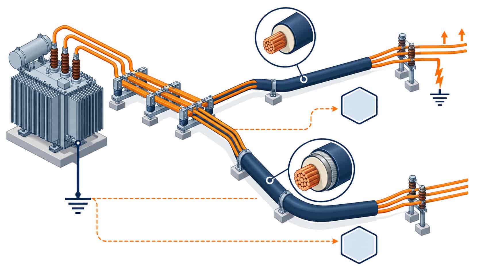
Every power system with a neutral presents its cable insulation with two simultaneous voltages: the phase-to-phase voltage between conductors, and the phase-to-earth voltage between each conductor and the grounded neutral. Cable insulation must sustain both continuously, plus the temporary over-voltages that faults create. Standards describe the requirement with the pair U0/U — the earth voltage first, the line voltage second — and construction tables for each class fix insulation thickness, screen design and test voltages accordingly. The complication, and the reason neighboring classes exist, is that a single earth fault changes the picture. In some earthing regimes the healthy phases jump to line voltage against earth until the fault clears, and the cable’s U0 must be chosen for that reality. The class decision is therefore a system decision, made before the cable is quoted — and it’s the first technical question a competent factory asks about any medium-voltage enquiry.
Reading U0/U: The Two Numbers and What Binds
U0 is the rated voltage between conductor and earth — the number the insulation’s continuous strength is built around. U is the rated voltage between conductors, which for three-phase systems is U0 times the square root of three. In an effectively earthed system — neutral solidly grounded — a phase-to-earth fault collapses that phase’s voltage and the healthy phases stay near their normal earth voltage, so U0 covering normal phase-to-earth service is sufficient, and the economical classes like 6.35/11 or 8.7/15 kV apply. In a non-effectively earthed system — isolated neutral, resonant earthed, or high-impedance earthed — a single earth fault does not open the circuit. The healthy phases rise to full line voltage against earth for as long as the fault persists, sometimes hours by design. Those systems need U0 at or near the line voltage, which is why the same 11 kV network can specify 6.35/11 kV in one plant and 8.7/15 kV-class insulation in another. The earthing regime is a system document answer, and the cable class reads from it — never from the transformer’s nameplate alone.
| Class (U0/U) | System Voltage Fit | Earthing Regime Fit | Typical Duty |
|---|---|---|---|
| 0.6/1 kV | 400/230 V LV networks | All regimes â thick enough either way | Panels, motors, building distribution |
| 3.6/6 kV | 6 kV systems | Effectively earthed | Plant MV motors, small feeders |
| 6/10 kV | 10 kV networks | Effectively earthed | Urban distribution, industrial incomers |
| 8.7/15 kV | 11-15 kV networks | Effectively earthed; higher U0 for non-effective | Primary distribution, transformer links |
| 12/20 kV | 20 kV networks | Effectively earthed; elevated-U0 variant | Regional distribution, renewables collection |
| 19/33 kV | 33 kV networks | Effectively earthed | Sub-transmission, large plant incomers |
| 26/35 kV | 35 kV networks | Effectively earthed; elevated-U0 variant | Utility feeders, wind and solar export links |
Insulation Thickness and the Cost of Class
Class is not a label; it is millimeters of insulation and a screen design. Each step up in U0 adds insulation thickness, which adds drum diameter, bending radius and cost — and at medium voltage adds the metallic screen system that controls the electric field across the thicker wall. This is why over-specifying the class is a real budget line: a project that buys 12/20 kV cable for an effectively-earthed 11 kV network pays a class premium on every meter for a scenario its earthing never creates. Under-specifying is worse and quieter. Insulation stressed beyond its U0 service doesn’t fail at commissioning — it ages in the dark, and partial discharge slowly drills the failure that appears years into service. The middle path is precision: read the earthing regime, pick the class that covers it, document the reasoning in the schedule. The construction consequences of each class — thickness, screens, tests — are the territory of the standard behind the cable families, explained in the IEC 60502 guide, and the wider IEC, GB and BS framework is mapped in our MV and LV standards guide.
The Temporary Over-Voltage Question
Between the continuous rating and the fault scenario lies the temporary over-voltage: earth-fault conditions, switching events and load-rejection transients that raise phase-to-earth voltage for seconds to hours. Standards express the cable’s tolerance in this dimension too, and the elevated-U0 classes exist precisely for networks where these events are frequent or long-lived — resonant-earthed rural networks, arc-suppression-coil systems, some industrial networks with high earth-fault current paths. The engineering question to put in the schedule is operational: what is the longest credible time the healthy phases sit above normal U0, and does the chosen class’s temporary over-voltage tolerance cover it? Factories answer this from their construction tables, which is why the earthing single-line diagram belongs in every MV enquiry — and why reading the offered cable’s full rating data, not just the headline class, is the discipline in our equipment datasheet reading guide.
Class in the Broader System: Accessories and Equipment
The voltage class propagates beyond the cable: joints and terminations are built per class with stress-control geometries, switchgear and transformers carry matching ratings, and the accessories for one class never rate for another. A schedule that fixes the cable class must fix the accessory class in the same breath — the termination stress cone for an 8.7/15 kV cable is a different product from the 6/10 kV one — and the accessory selection discipline is its own checklist in our cable accessories guide. On the equipment side, the switchgear on either end of the feeder carries its own class grammar, governed by its own standard as decoded in our IEC 62271 switchgear guide, and the transformer’s vector and earthing arrangement is what creates the regime in the first place — the standard behind it is decoded in our IEC 60076 transformer guide. Class coherence across the chain — cable, accessories, switchgear, transformer — is what the class decision actually buys.
| Earthing Regime | Fault Behavior | U0 Principle | Example Class |
|---|---|---|---|
| Solidly earthed neutral | Fault clears fast; healthy phases near normal | U0 covers normal phase-to-earth service | 6/10 or 8.7/15 for 11 kV |
| Resistance earthed | Fault clears with delay | U0 covers service plus limited rise | Next elevated class where delay is long |
| Isolated neutral | Fault persists; healthy phases at line voltage | U0 at or near line voltage | 8.7/15 class on 11 kV networks |
| Resonant earthed (Petersen coil) | Fault self-clears; long over-voltage windows | Elevated U0 with TOV margin | Check temporary over-voltage table |
When the Class Grammar Is Not the Answer
The U0/U system describes AC power cable insulation, and its edges matter. DC systems — traction, HVDC, some solar architectures — use a different stress grammar entirely, and an AC class quoted at a DC voltage is a category error. For low-voltage installations, the 0.6/1 kV class covers all earthing regimes and the decision collapses to selecting the right construction instead. Above 35 kV, the high-voltage standards take over with their own class definitions and test worlds. And where a destination market quotes its own historical class names — North American kV mil-spec traditions, for instance — the translation to U0/U needs a conscious mapping, not a hopeful search-and-replace. Within its territory, though, the grammar is universal, and the project that documents its earthing regime once can quote every cable in the plant from the same table.
RFQ Checklist: Specifying the Voltage Class
Make the class decision auditable, so include:
- System voltage and earthing regime stated (solid, resistance, isolated, resonant)
- U0/U class explicit per circuit, with the earthing reasoning noted
- Maximum earth-fault clearing time stated for the temporary over-voltage check
- Governing standard and part cited (e.g. IEC 60502-2 for the class range)
- Accessories class-matched: joints and terminations at the same U0/U
- Equipment class coherence checked: switchgear, transformer, surge arresters
- Routine and type test evidence required naming the tested class
- Destination-market class names mapped to U0/U for the inspector
- Single-line diagram attached so the factory verifies the regime independently
- Any elevated-U0 requirement flagged with its operational justification
Conclusion
The voltage rating is two answers to two questions, and the earthing regime decides which question dominates. Read the single-line diagram, pick U0 for the earth-fault reality, name the class with its standard — and the most misunderstood line in the cable schedule becomes the most defensible one.
Kexingyu Cable Group (KXYE) manufactures across the 0.6/1 kV to 26/35 kV classes with routine and type-test evidence per class, and reviews the earthing regime with every MV enquiry — so the class in your schedule arrives built for the system it will live in, tested and export-ready.


