
Drag Chain Cable Anatomy: Every Layer Explained From Copper to Jacket
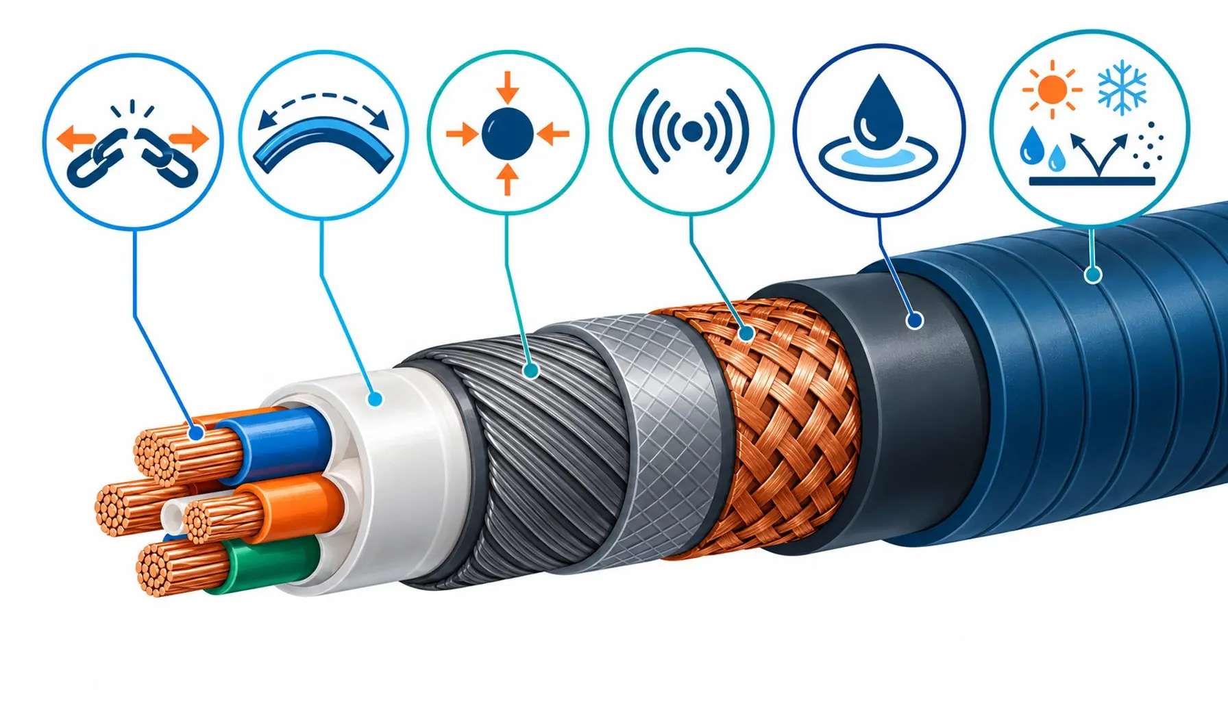
Quick Answer: A drag chain cable is six cooperating layers, each engineered against a specific failure mode; understanding what each layer contributes turns cable selection from name recognition into engineering judgment.
Chain cable catalogs are full of names: chain-rated, high-flex, gliding, continuous-flex, and the names say nothing about what is actually inside. The inside is where the differences live. Two cables can carry the same jacket label and differ by a factor of ten in service life because of decisions made at four layers the buyer never sees. This guide opens a drag chain cable layer by layer, from the copper outward, and for each layer explains what it does, what it is made of, how it fails, and what a buyer should verify. It is the anatomy lesson behind every other article in this series: once you know what each layer contributes, the specification questions write themselves.
Introduction
The way to read a cable is to ask, at each layer, what enemy that layer is fighting. A cable in a chain faces five enemies at once: bending strain at the conductor, electrical stress between elements, interference between noisy and quiet signals, abrasion inside the chain, and the chemistry of the machine environment. A well-built chain cable assigns each enemy to a layer built specifically against it, and the layers cooperate: the finest engineering at one layer cannot rescue a cheap decision at another. That cooperation is why anatomy matters. The layer that fails first sets the life of the whole cable, and the buyer who cannot see the layers is buying the average of someone else’s trade-offs.
Layer One: The Conductor, Where Flex Life Begins
At the center of everything is the copper, and in a chain cable it is never coarse. Flex-duty conductors use fine strands, Class 6 or finer, twisted at short lay so that bending strain is shared among hundreds of wires instead of concentrated in a few. The geometry, strand count, strand diameter, lay length and the alternating directions of successive layers, is the single biggest determinant of how many bending cycles the cable survives. It is also the layer most often substituted in cheap products, because inside the jacket a coarse conductor is visually indistinguishable from a fine one.
What to verify: the construction sheet stating strand count and lay, and flex-cycle test data from the finished cable. The field check is simpler: strip a sample and count wires, a ten-minute audit, and the failures that follow skipped construction steps are catalogued in the guide to why cables fail.
Layer Two: Insulation, Where Electrical Discipline Lives
Each conductor carries its own insulation, and in chain cable the insulation does more than dielectric duty: its surface friction and stiffness set how the cores slide against each other through every bend. Motion-grade insulations are chosen for low stick-slip and stable flexibility across the temperature range, with cross-linked compounds where thermal headroom or switching stress demands them, the chemistry shared with the static-cable grades compared in the guide to XLPE insulation. Color coding and printing live here too, and on hybrid cables the insulation scheme is what keeps the power, brake and signal elements identifiable through a million cycles of handling.
What to verify: insulation material named on the datasheet, temperature range matching the machine, and for servo constructions, partial-discharge data if the drive runs hard edges, the switching environment created by the drives compared in the guide to drives and soft starters.
Layer Three: The Bundle Geometry, Where Organization Lives
Between the insulated cores and the shield sits the least discussed and most characteristically chain-cable layer: the arrangement. Cores are twisted into bundles, bundles into a short-lay overall twist around a central element, and the pitch of that assembly is engineered so that bending strain stays shared and the bundle stays compact through the cycle. Flexible fillers and binders keep the geometry round without locking it. Torsion-duty variants change the rules here, with longer lays in alternating directions to hold angular reserve while the machine rotates.
What to verify: cut the cable open and the geometry is visible at a glance, short consistent lays, a central element, no loose cores rattling in dead space. A sloppy bundle is visible evidence of a maker who skipped the invisible steps, and the jacket will not compensate for it.
Layer Four: The Shield, Where Signal Protection Lives
Where the cable carries signals, encoder pairs, communication buses, instrumentation, the shield is the boundary between the noisy power elements and the quiet ones, and between the whole cable and the drive switching around it. Chain-duty shields are dense braids, often with foil companions for full coverage, engineered to survive flexing rather than merely to exist. The shield’s electrical value survives only through its terminations, and the grounding architecture that keeps a shield at low impedance starts with the cabinet-side practice described in the guide to control cabinet construction.
What to verify: braid coverage figures, shield continuity through the supplier’s flex test, and for hybrid cables, individual shields around the sensitive pairs rather than one shield shared by everything.
Layer Five: The Inner Sheath, Where Containment Lives
Many chain cables wrap the shielded core assembly in an inner sheath before the jacket goes on. Its jobs are containment and interface: it holds the bundle geometry, gives the shield a stable bedding, and creates a low-friction interface so the outer jacket can slide against the core assembly instead of dragging it. In demanding constructions the inner sheath is the same compound family as the jacket, and in the toughest builds it is textile-reinforced. The layer is optional in light-duty cables, and its presence is one of the visible markers distinguishing genuine chain-rated products from repackaged flexible cable.
What to verify: whether the construction includes it, and if the supplier’s cutaway images show it, that the images match the delivered product. The cutaway is the honest sales document in this market, and suppliers proud of their construction publish it.
Layer Six: The Jacket, Where the Environment Is Fought
The outer jacket is the layer the chain and the machine actually touch, and it fights abrasion, oil, coolant, chips and cold. PUR dominates machine-tool duty for its combination of abrasion resistance and oil resistance; TPE takes the cold and chemistry niches; PVC remains acceptable only in dry, benign interiors. The jacket compound choice is a whole subject of its own, with the insulation-side chemistry shared with the grades compared in the guide to XLPE versus PVC, and where mechanical strike competes with abrasion, the protection trade-offs are compared in the guide to armored versus unarmored cable.
What to verify: compound named and tested against the machine’s fluids, surface friction suitable for chain dividers, and jacket thickness consistent with the duty. The jacket is the layer everyone evaluates; the anatomy lesson of this article is that it is one of six, and rarely the layer that fails first. When a cable does fail, the layer that surrendered tells the story, and the field guide below maps the visible signatures back to their layers.
| Layer | Enemy it fights | Typical materials and geometry | How to verify |
|---|---|---|---|
| Conductor | Bending strain concentration | Class 6 or finer strands, short lay, alternating layer directions | Construction sheet; strip and count; flex-cycle data |
| Insulation | Electrical stress, stick-slip between cores | Low-friction compounds, cross-linked where duty demands | Material named; temperature range; PD data for servo duty |
| Bundle geometry | Strain sharing, compactness | Short-lay overall twist, central element, flexible fillers | Visible in cutaway: consistent lays, no dead space |
| Shield | Interference between and around elements | Dense braid, foil companion, individual shields on sensitive pairs | Coverage figures; continuity through flex test |
| Inner sheath | Containment and jacket interface | Low-friction compound, sometimes textile reinforced | Presence in construction sheet and cutaway images |
| Jacket | Abrasion, oil, coolant, chips, cold | PUR default, TPE for cold, specialty for extremes | Compound named and tested against the machine's fluids |
The Anatomy Summary Table
The layers, their enemies and their verification compress into one table, which is the reference version of this article and the template for auditing any supplier’s construction sheet.
| What you see on the failed cable | Layer that failed | Mechanism | Specification gap it exposes |
|---|---|---|---|
| Broken conductors at one bend zone, jacket intact | Conductor | Fatigue from strain concentration | Lay geometry or class below the duty |
| Pair-to-pair or pair-to-shield leakage | Insulation | Dielectric stress or abrasion through insulation | Compound or thickness below duty; hybrid separation missing |
| Core bundle loosened, dead space, rattle | Bundle geometry | Geometry collapse under cycling | Shortcut assembly; no engineered lay or central element |
| Feedback noise rising with cycle count | Shield | Braid fatigue and coverage loss | Shield not flex-engineered; termination practice weak |
| Inner cores visible through jacket splits | Inner sheath or jacket | Abrasion through containment | Jacket compound or thickness below the chain duty |
| Jacket swollen, sticky or cracked | Jacket | Fluid attack or cold exposure | Compound never tested against the machine's environment |
When Anatomy Knowledge Is Not Enough
Honest limits: knowing the layers does not replace knowing the duty. The best-built cable in the wrong application fails the same as the worst; anatomy enables specification, and specification requires the machine’s numbers, radius, cycles, fluids, temperature and signals, which no cutaway can supply. There are also constructions where layers merge or disappear: flat cables in chains reorganize the geometry entirely, miniature robot cables compress the stack, and bus cables add their own impedance-controlled pair designs. The anatomy here is the reference pattern of round chain cable, and the variations are judged against it, not instead of it. And anatomy does not end the lifecycle: terminations, routing and maintenance decide whether the engineered layers get to finish their work, subjects the broader guides in this series treat in full.
RFQ Checklist: Auditing a Chain Cable Construction
Bring the anatomy to the supplier as questions:
- Construction sheet required: strand count, lay length, insulation compounds, bundle lay, shield coverage, sheath and jacket compounds
- Cutaway image or sample section of the actual offered construction
- Flex-cycle test data from the finished cable at your radius, with failure criterion stated
- Fluid and temperature test data matching the machine environment
- For hybrid constructions: separation and shielding architecture of sensitive pairs
- Consistency statement: what process data proves the delivered reels match the tested sample
Conclusion
A drag chain cable is six layers built against six enemies, and the order of their failure is the order of the buyer’s priorities. Conductor geometry sets the ceiling on flex life; insulation and bundle geometry preserve it; the shield protects the signals the machine depends on; the inner sheath and jacket fight the environment the machine deals out. Every honest supplier can document all six; every careful buyer should ask for all six, because the layer that fails first was always the one nobody asked about.
Kexingyu Cable Group (KXYE) publishes construction sheets and cutaway documentation for its chain cable range, layer by layer, with flex-cycle evidence from the finished construction. Send your duty through the RFQ page, and we will show you the anatomy before you commit to it.


