
Encoder Cable: Keeping Feedback Signals Clean at Full Speed
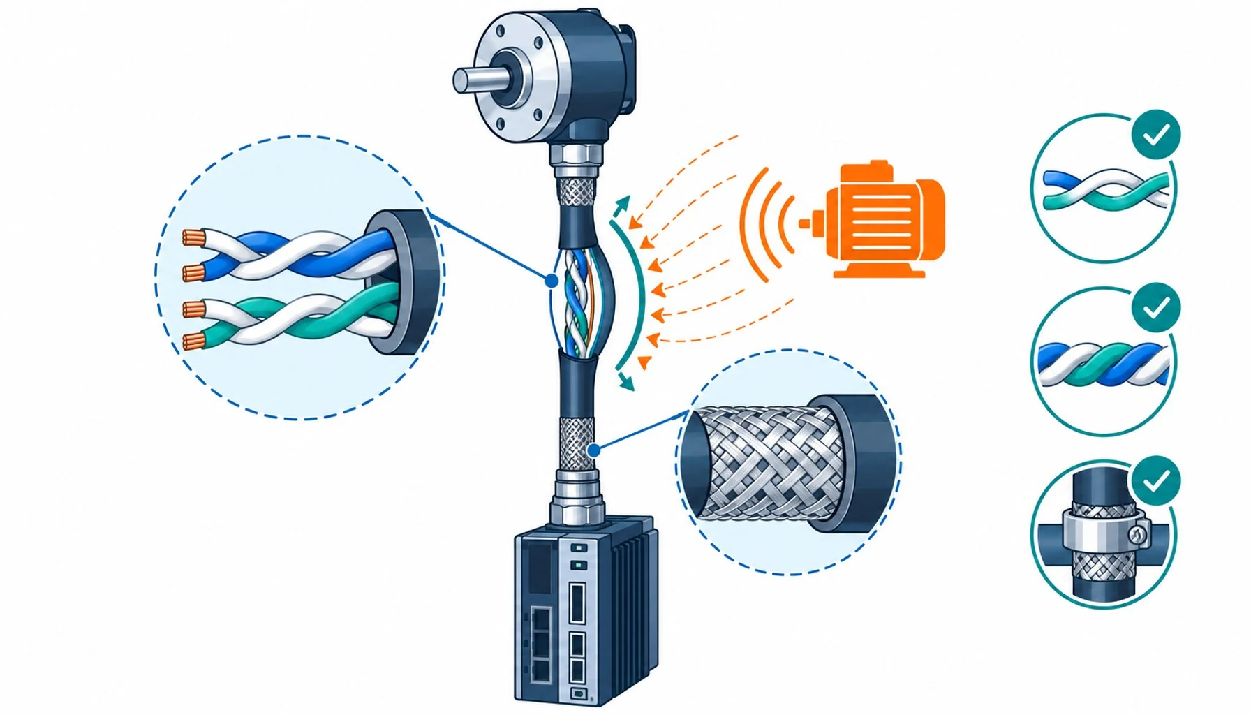
Quick Answer: An encoder cable carries the position signal a drive trusts absolutely; clean feedback at speed depends on balanced twisted pairs, a flex-rated braid shield and terminations that survive the same motion the cable does.
Of all the cables on a machine, the encoder cable has the strangest job: it carries the one signal the drive believes without question. Power conductors can sag and recover, communication buses can retry, but if the encoder signal glitches, the drive acts on the glitch instantly, and the machine jerks, faults or loses position in the time it takes a control system to notice anything is wrong. This asymmetry is why encoder cable deserves its own engineering attention, separate from the power conductors it usually runs beside. The signal is small, often millivolt-class differential, and the environment it crosses is the most electrically hostile spot in the plant: centimeters from motor power carrying switched currents with nanosecond edges.
Introduction
Encoders come in families with different appetites: incremental sinewave signals that are exquisitely sensitive to amplitude distortion, absolute encoders with serial communication layers, resolvers with their own analog logic. What they share is small differential signals that depend on pair balance for their noise rejection. The receiver at the drive reads the difference between the two wires of a pair; interference that arrives equally on both wires cancels. Everything in encoder cable design serves that cancellation: the pair’s symmetry, the consistency of its twist, the shield that intercepts what the balance cannot reject, and the ground architecture that gives interference somewhere to go that is not the signal.
The failure signature of a compromised encoder cable is distinctive and worth learning early: position errors that correlate with speed or torque, faults at specific machine positions, drives that trip on feedback error after years of quiet running, and the fault families behind those trips overlap with the patterns catalogued in the guide to common inverter failures. The symptoms mean the noise has found a path past the defenses, and the path is almost always a termination, a damaged pair or a shield that motion has degraded.
Pair Design: Where the Signal Integrity Lives
The heart of encoder cable is the twisted pair, and the details matter more than any datasheet summary suggests. The two conductors of each signal pair must be electrically symmetric: same geometry, same insulation, same distance to everything around them, twisted together at a consistent pitch. Symmetry is what makes interference common-mode so the receiver can reject it; asymmetry converts interference into differential noise that no receiver can reject. Pairs carrying different signals are twisted at different pitches so that crosstalk between pairs does not accumulate in phase along the cable length.
Power elements inside the same cable, when the encoder pairs share a hybrid construction with motor power cores, add a further requirement: physical separation and individual shields around the sensitive pairs. The discipline of what lives inside one jacket and what lives separately is the subject of hybrid cable design more broadly, and encoder pairs are always the elements that set the strictest requirements in that negotiation. The table below summarizes the signal families a harness may carry and the pair requirements each one brings.
| Check | Method | Pass condition | What failure indicates |
|---|---|---|---|
| Pair integrity | Continuity and insulation test pair to pair and to shield | Low resistance in pair, high to everything else | Conductor fatigue or insulation damage inside the flexing section |
| Shield continuity and bonding | Measure shield end to end and to ground at both ends | Low and stable; machine position should not change it | Braid fatigue or a degraded clamp; the classic silent failure |
| Termination geometry | Open the gland or connector; inspect twist retention and clamp | Twists intact to the landing, 360-degree shield contact | Pigtails and un-twisted stubs converting the shield into an antenna |
| Separation from power | Open the carrier along the run | Power and encoder sections separated, crossings at right angles | Bundle migration; interference coupling that grows with speed |
| Noise correlation | Drive diagnostics: map faults against position and speed | No position or speed correlation | Correlated faults point at the harness segment at that position |
| Contact resistance at connectors | Measure through mating connector ends | Milliohm class, stable after re-mating | Worn or contaminated contacts; replace rather than clean and hope |
Shielding: The Second Line and Its Motion Problem
Pair balance rejects interference that arrives equally; the shield intercepts what arrives unevenly and what radiates. Encoder cable conventionally carries a dense braid over the pairs, often with foil for full coverage, and the braid’s job on a moving axis is doubly hard: it must intercept interference while itself surviving the flexing. Braid fatigue under motion, and the grounding architecture that keeps the shield at low impedance at both ends, follow the grounding discipline used across drive-fed machines, described in the guide to control cabinet construction, and the same physics applies with extra urgency here because the signal inside is smaller than anywhere else on the machine.
The shield’s value collapses at its terminations. A 360-degree clamp at the drive end and the same discipline at the sensor end preserve the geometry; a pigtail gathered under a terminal turns the shield into an impedance spike exactly where the noise is most unwelcome. On a moving axis the termination also carries mechanical duty, and separating the flex stress from the current path is the detail that separates terminations that last from terminations that become the fault.
Flex Construction: Why an Encoder Cable Moves Differently
Static encoder runs, from a fixed sensor to a terminal strip, are ordinary instrumentation work. Motion changes everything: the pairs must be laid with flex-rated stranding so the small conductors survive cycling, the pair twist must hold its geometry through bending, and the overall construction must be compact enough for the carrier space the machine gives it. Encoder pairs are among the finest conductors on the machine, which makes them the most fragile, and the flex engineering that protects power cores is proportionally more critical here. The conductor geometry behind that protection follows the same fine-stranding logic as any flex-rated power cable, and the failure modes that appear when construction is skipped are catalogued in the guide to why cables fail, with the shield and jacket decisions following the same motion-cable logic.
Routing completes the flex design: service loops at the sensor, bend radius respected at the tightest point rather than on average, and separation from power runs inside the carrier, crossing at right angles where crossing is unavoidable. A well-built encoder cable in a careless routing fails exactly like a cheap one, which is why the installation rules are part of the cable specification rather than a footnote to it.
Wiring Discipline at the Ends
Most encoder problems that are not cable-internal live at the ends. The rules are old and proven: keep the pair twists intact up to the termination point, un-twisting only the minimum length needed to land the conductors; land the pair symmetrically at the receiver, respecting the differential layout; never share the pair’s return with unrelated grounds; and keep the shield’s 360-degree path continuous from cable to connector body to drive chassis. Incremental sinewave encoders add strictness on pair length matching and on the quality of the connector contact resistance; absolute encoders with serial layers add requirements on the communication pairs that follow bus-grade practice.
The table below condenses the wiring discipline into the checks a commissioning or troubleshooting visit actually performs, in the order a methodical technician would run them.
| Signal family | Sensitivity | Pair requirement | Typical mistake |
|---|---|---|---|
| Incremental sinewave (A/B analog) | Highest, amplitude and phase matter | Individually shielded pairs, matched lengths, consistent twist | Sharing a shield with power or treating pairs as interchangeable |
| Incremental square (5V TTL class) | High, edge integrity matters | Tight twist, individual or grouped shield | Long un-twisted stubs at termination |
| Absolute serial (bus-based) | Moderate, protocol retries mask small noise | Bus-grade pair practice, controlled impedance where specified | Assuming retries make shielding optional; retries cost cycle time |
| Resolver analog | High, low-frequency analog discipline | Shielded pairs, attention to ground reference | Ground loops through the shield at both ends without architecture |
| Safety-rated feedback | Highest, with integrity obligations | Dedicated pairs, separation, documented shield practice | Reusing general harness segments for safety signals |
When Encoder Problems Are Not the Cable
Honest limits: the cable is one link in a feedback chain, and disciplined troubleshooting checks the neighbors before condemning it. The encoder itself ages, bearings and optics degrade, and its failure signatures overlap with cable noise. The drive’s receiver electronics and its grounding reference matter: a receiver measuring against a drifting ground reads noise that a perfect cable cannot prevent. Firmware and parameter changes occasionally masquerade as hardware faults when feedback filtering settings shift. And some installations blame the encoder cable for bus-level problems that belong to the communication architecture, where the instrumentation separation logic described in the guide to control versus instrumentation cable was never applied in the first place. The methodical sequence, cable checklist first because it is fastest, then sensor, then drive, resolves most cases in one visit.
RFQ Checklist: Specifying Encoder Cable
Bring the feedback duty to the supplier in specifics:
- Signal inventory: encoder type and protocol, pair count, any hybrid power cores sharing the jacket
- Motion duty: radius, cycles, speed, twist if the axis rotates
- Interference environment: drive power in the same carrier, switching frequency, cable length
- Evidence required: flex-cycle data with pair continuity and shield condition at end of test
- Shield and termination system: braid construction, 360-degree gland or connector options
- Documentation: pair pitch and symmetry data, not just a pair count on a datasheet line
Conclusion
Encoder cable carries the smallest signal on the machine through the loudest environment, and the drive acts on whatever arrives without hesitation. That asymmetry is why the discipline is strict: balanced pairs with consistent twist, a flex-rated shield terminated 360 degrees at both ends, motion-graded construction, and routing that keeps the sensitive pairs away from the power that would corrupt them. None of it is expensive relative to the downtime it prevents, and all of it is verifiable with measurements a maintenance team already knows how to take.
Kexingyu Cable Group (KXYE) builds encoder cable with individually shielded, flex-rated pairs and hybrid constructions for combined servo duty, with test evidence that follows the signal, not just the jacket. Send your feedback circuit duty through the RFQ page, and we will match the pair design to the signal the machine depends on.


