
Gantry and Portal Systems: Cable Carriers on Long-Travel Axes
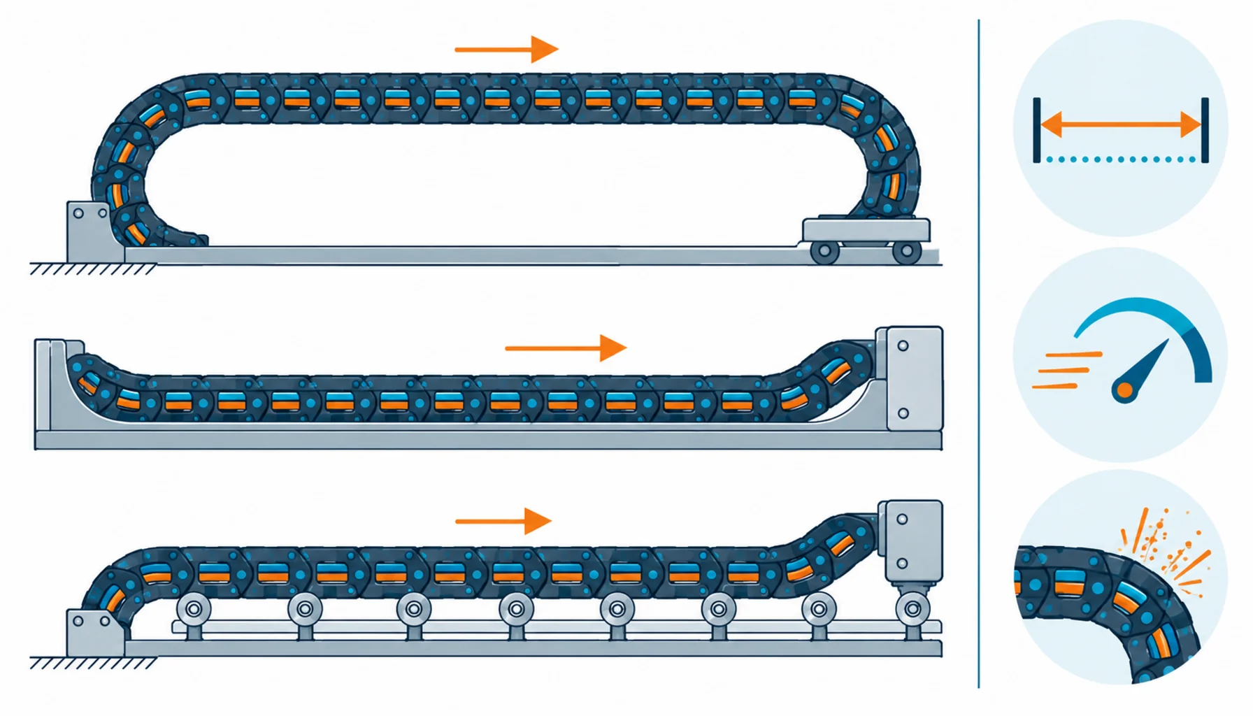
Quick Answer: On gantry axes past ten meters of travel, the cable carrier becomes a structural system — gliding or rolling layout, self-supporting span and acceleration loads decide how the chain and its cables must be built.
Everything that makes cable chains work on a milling machine gets harder when the axis is a runway. A gantry or portal machine moves its cable carrier through ten, twenty, sometimes a hundred meters of travel, and the chain stops being a plastic accessory and becomes a piece of mechanical engineering. The unsupported span between fix points grows until the chain must ride on itself or in a trough. Acceleration loads at each reversal — on a portal milling machine or a container crane trolley, the moving mass is measured in tons — yank the chain and everything inside it. And the cables inside the chain now include heavy power feeds and precision data lines that have to arrive at the far end intact after years of being dragged, flexed and braked. This guide covers what changes for cable carriers on long-travel axes, and how to specify the system so a 40-meter axis does not become a 40-meter maintenance lesson.
Introduction
Gantries and portals put cable carriers in their harshest role. On a short axis, the chain self-supports its upper run and the design questions are bend radius and fill. On a long axis, gravity joins the conversation: past a certain length — a few tens of meters for most chain families — the upper run cannot hold itself, and the installation must switch to a gliding arrangement in a trough, a rolling configuration on rails, or a supported layout with guides. Each arrangement changes how the cables inside experience the motion, and each has its own limits on speed and acceleration. The selection logic is as much mechanical as electrical, which surprises teams who treat the chain as a harness accessory.
The electrical stakes scale with the machine. A gantry crane, a portal machining center, a plasma cutting table or a stacker crane carries drive power, control and increasingly real-time data down the same runway. The failure consequences scale too: on a 60-meter axis, replacing a failed cable is a day of production plus a logistics exercise, not an hour of maintenance. The failure patterns documented in the common causes of cable failure — breaks at transitions, shield damage, jacket wear — all reappear on long axes with the added stress of sheer scale.
Gliding, Rolling, or Self-Supporting: Choosing the Arrangement
The first design decision on a long axis is not the cable — it is how the chain travels. Below roughly 20 to 30 meters depending on chain type, a self-supporting upper run works: the chain cantilevers its own weight and the cables between the fixed points. Beyond that, the upper run sags, and sag means uncontrolled bend radius at the ends of travel — the exact mechanism that kills cables early. The standard solutions:
Gliding arrangement. The lower run slides in a trough lined with low-friction material. This is the economical default for long, slow axes — but speed and acceleration are limited by sliding friction and heat, and the trough adds installation work. Cable jackets need abrasion resistance because the lower run lives in contact.
Rolling arrangement. Rollers on the chain links ride the trough, cutting friction dramatically. Rolling chains handle long travels at higher speeds — portal machines and crane trolleys live here — at higher component cost and with more parts to maintain.
Guided or supported runs. For very long travels, intermediate guides or support rollers break the span into sections the chain can handle. The design rule is constant: the cable’s bend radius must be respected everywhere, all the time, including the moments of maximum acceleration.
| Arrangement | Typical Travel | Speed and Duty | Watch Out For |
|---|---|---|---|
| Self-supporting | Up to roughly 20-30 m depending on chain | Moderate speeds and accelerations | Sag at long spans; overstated unsupported length claims |
| Gliding in trough | Tens of meters | Long, steady strokes; limited acceleration | Jacket abrasion on the lower run; trough friction at speed |
| Rolling on rails | Tens to 100+ meters | High speed, high acceleration, portal-class duty | Roller maintenance; alignment; cost of the running gear |
| Guided / supported | Very long travels | Duty of the base machine | Guide wear; span calculations neglected after retrofits |
Acceleration: The Load Case Nobody Quotes
Gantry duty is defined by acceleration, not speed. A portal milling machine reverses its ram head at high acceleration thousands of times a day; a crane trolley does the same with far more mass. Every reversal sends a force wave down the chain and into the cable terminations. Two consequences follow. First, strain relief becomes a primary design element: the terminations at both ends must hold the dynamic loads of the full moving system for years, and the cable needs a strain-carrying core so those loads never reach the copper. Second, the chain’s connecting hardware and the fixed-end geometry must be engineered for the forces, because a chain that shifts at its fix point translates that shift into bend radius violations at the cable glands.
The cables themselves experience acceleration as repeated longitudinal loading. Conductors work against their stranding lay, jackets stretch slightly at every start and stop, and over millions of cycles the weakest point — usually a gland transition or a sharp fixture edge — begins the fatigue clock. High-flex constructions with short-lay stranding and aramid cores exist precisely for this load case; the sizing discipline that supports it starts with honest acceleration data in the specification, the same way conductor sizing starts with honest load data.
What Rides in a Gantry Chain
Long-travel chains carry a heavier and more varied load list than machine-tool chains. Drive power for the axis motors is often substantial — gantry axes are big motors — and the cable runs are long enough that voltage drop becomes a real design input, not a footnote. Control and safety circuits ride the same runway, with the separation and shielding discipline that keeps them clean next to the power feeds, the same logic behind power versus signal cable choices. Modern gantries increasingly add industrial Ethernet or servo feedback on the moving axis, and those data cables are the least tolerant passengers in the chain: they want the gentlest bend radius available and protection from the heavy power cables beside them.
Fill and weight distribution decide whether all of this coexists for a decade or fights itself for a year. Heavy power cables belong at the bottom or outside of the bundle so their weight does not crush data lines; dividers separate families; the total fill stays well under the chain’s limit because a packed chain at 40 meters has nowhere to shed heat or rub without consequence. Weight also feeds back into the mechanical design — chain pitch, trough depth, roller ratings — which is why the cable schedule belongs in the chain selection meeting, not after it.
Environment and Maintenance at Scale
Long axes live outdoors or in raw industrial halls more often than machine tools do. UV, temperature swing, dust, and on cranes salt air all act on the chain and its cables for decades of service. Jackets chosen for the actual exposure — UV-stabilized compounds, abrasion-resistant covers on gliding runs, temperature-rated materials for cold-store gantries — determine whether the system ages predictably. Maintenance matters at scale too: trough inspection, chain link and roller checks, and jacket condition review at the fixed ends catch the small failures that become 40-meter problems. The electrical infrastructure around the axis — the panels and drives the chain feeds — follows the same maintenance logic as any motor control installation, but the harness between panel and motion is the part that moves, and moving parts earn their inspection schedule.
| Check | What to Pin Down | Why It Decides the Outcome |
|---|---|---|
| Travel and duty | Stroke length, speed, acceleration, cycles per day, reversal pattern | Chooses the arrangement and the flex life requirement |
| Arrangement | Self-supporting, gliding, rolling or guided — with the math shown | Sag or friction at the wrong speed kills cables on schedule |
| Cable schedule | Power, control and data cables with weights, diameters and separation | Fill, dividers and weight order are decided here |
| Terminations | Strain relief rated for dynamic acceleration loads at both ends | Reversal forces land on the glands; they must be engineered |
| Environment | Indoor or outdoor, UV, temperature band, dust, salt, washdown | Jacket and chain material follow the exposure, not the catalog |
| Maintenance plan | Trough and chain inspection points, jacket checks, spare lengths | At 40 meters, small failures are expensive ones |
When a Gantry Cable Carrier Is Not the Answer
Honesty about scope keeps this guide useful. Cable carriers excel at guided, back-and-forth travel on a known path. Three situations want something else. Continuous rotation — slew rings, rotating platforms — puts torsion into the cables that no chain absorbs; that is torsion cable territory. Cable-on-spool duty such as crane hoists and reeling drums adds winding stresses beyond chain design, covered in the cable reel applications guide. And very short, fast axes where a chain adds cost without benefit sometimes suit free-looping continuous-flex designs. Gantry-style carriers also do not solve building-side power distribution for the machine; the feeders, protection and grounding behind the axis remain installation engineering, planned with the site’s power distribution review. Match the delivery system to the motion, and the cables inside it will do their part.
RFQ Checklist: What to Send the Supplier
Put the axis’s reality in writing before quotes come back:
- Travel, speed, acceleration and duty cycles, with the reversal pattern stated honestly
- Proposed arrangement: self-supporting, gliding, rolling or guided, with span calculations
- Cable schedule: families, diameters, weights and separation requirements for the chain
- Termination loads: dynamic forces at the fix points, strain relief requirements
- Environment: indoor or outdoor exposure, temperature band, UV, dust, salt or washdown
- Required flex life with the test method that will verify it
- Spares plan: cable lengths, pre-terminated ends where possible, batch traceability
Conclusion
On long-travel gantries the cable carrier is a structural system, and the cables inside it are rated components of that system. Choose the arrangement from real travel, speed and acceleration data; engineer the terminations for dynamic loads; schedule the cables by family with weight and separation in mind — and a 40-meter axis runs for decades. Skip the mechanics and no cable brand rescues the installation.
Kexingyu Cable Group (KXYE) supplies high-flex cable constructions engineered for long-travel duty — aramid-cored power feeds, motion-grade control and data cables — with flex data and batch traceability behind every rating. Send your axis travel and acceleration profile through the RFQ page, and we will quote the cable schedule against the mechanics, not after them.


