Generator-to-ATS Cable Connections: Backup Power Done Right
Quick Answer: Generator cable sizing is a derating-and-termination exercise: the run must carry full load current at elevated temperatures, survive vibration and hold voltage drop low for clean transfer. When the utility supply fails, the generator-to-ATS cable becomes the most important run of copper in the building. It carries the entire critical load at the moment of transfer, often after hours of sitting idle, and it does so in a generator room that is hotter and louder than any other electrical space. Yet this run is frequently sized by habit — copied from the generator breaker frame rather than calculated from the real load and the real environment.
Introduction
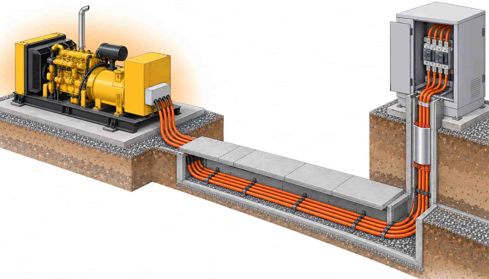
Standby power architecture is simple on the single-line diagram: generator, transfer switch, critical bus. The cable between them is where the physics gets inconvenient. Current on this run is continuous for the duration of the outage, ambient in the plant room sits above design norms, and the load can arrive in one block the instant the ATS closes. Every one of those conditions pushes conductor size upward, and missing any of them produces a feeder that tests fine on a cool day and trips during a summer outage.
This article walks the connection from both ends: what the generator side demands of the cable, what the ATS side demands, and what happens in the middle — ampacity, voltage drop, termination flexibility and fire routing. The transfer switch itself is only half the decision at that node; our comparison of ATS versus STS transfer technologies covers the switching logic. And because generator plants rarely stand alone in critical facilities, the hybrid topology of generator plus battery storage systems changes where these feeders run — worth reading alongside this guide.
What the Generator Side Demands
Generator terminals move. Engine vibration, thermal growth and routine maintenance all work the termination, which is why generator-side cable should always be fine-stranded Class 5 flexible conductor with a flexing loop provision at the gland plate — never rigid single-core sets pulled tight. The insulation must hold 90 °C continuous operation because the machine room rarely stays at the 30 °C that ampacity tables assume, and where the run passes through an outdoor trench or riser, UV and moisture resistance join the specification.
Sizing starts from the generator’s continuous rating but must respect its overload behavior. Many standby sets deliver 110% of nameplate for limited periods; a cable sized exactly to nameplate has no margin for that duty, and protection coordination may permit currents that cook an undersized feeder long before the engine complains. Practical practice: size the conductor to the generator breaker’s setting with derating applied, not to the generator nameplate. The correction-factor method behind this is walked through in our cable size selection guide.
| Factor | Effect on the Cable | Design Response |
|---|---|---|
| Sustained full-load current | Run carries the whole critical load for the outage duration | Size to breaker setting, not generator nameplate; verify thermal capability |
| High plant-room ambient | Engine rooms commonly run 40-45 °C at cable height | Ambient correction factor applied to every route; measure, do not assume |
| Block load transfer | Full current appears the instant the ATS closes | No diversity credit on this run; thermal margin preserved end to end |
| Termination vibration | Engine movement fatigues rigid terminations | Class 5 flexible stranding with a flexing loop at the generator gland |
| Voltage drop at transfer | Excessive drop sags the bus during block pickup | Keep run voltage drop within the ATS and load tolerance window |
| Fire exposure in risers | Shared risers put the backup path next to the hazard | Fire-rated construction or protected routing for riser sections |
What the ATS Side Demands
The transfer switch sees the worst electrical moment in the building: both sources live, full block load about to land, and the bus already sagged by the outage. Cable voltage drop on the generator run eats into the margin the ATS and downstream loads need to ride through that pickup. Long runs — generator yards at the property line are common for noise and fuel reasons — make voltage drop, not ampacity, the governing criterion. A route that passes ampacity at 95 mm² can demand 150 mm² or parallel sets purely to hold drop within limits over 150 metres.
The ATS enclosure itself constrains termination: lugs accept a maximum conductor range, and parallel sets need proper splitting hardware. Order the cable with the termination in mind — same cross-section per phase, Class 5 stranding where the gland geometry bends the conductor, and drum lengths cut to the routed measurement rather than nominal building dimensions.
Medium Voltage Generator Plants Change the Cable Family
As critical facilities grow, generator plants step up to medium voltage — packages in the 2,000-2,500 kVA class at 11 kV are now standard in large data centers, synchronized in multiples behind a single section of MV switchgear. The feeder family changes accordingly: 8.7/15 kV XLPE cable with screened construction, earthing schemes and non-magnetic containment for single-core runs, governed by the same rules as any MV distribution circuit — our overview of MV cable standards across IEC, GB and BS applies unchanged. What the generator adds is vibration at one end and a narrower switchroom at the other, so flexible MV terminations and careful gland coordination matter more than in a utility intake.
Multiple generator sets also mean multiple feeder runs converging on the synchronizing bus. Routing discipline pays here: identical set lengths per phase, labeled both ends, and drum lengths coordinated so parallel sets land without mid-route joints. Projects that treat these runs as ordinary power cable always rediscover why synchronization plants are engineered — our guide to generator synchronization systems covers the switchgear logic those feeders serve.
Routing, Fire Performance and the Life-Safety Overlap
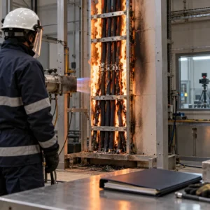
The physical route between generator and ATS decides several cable properties at once. Where the run shares a riser or corridor with life-safety circuits or passes through fire compartments, the specification may demand fire-rated construction — mineral insulated BTTZ or flexible BBTRZ / NG-A (BTLY) — so the backup path survives the same event that started the outage. Where the run is outdoor trench, sheath abrasion, rodent protection and water resistance dominate. Where it crosses between buildings, the earthing arrangement of screens and armor needs an explicit design decision rather than a field improvisation.
Plant rooms also concentrate heat from the generator itself. Cable trays routed above the engine canopy or within the radiator airflow see ambient far above room temperature, and grouping in those shared trays compounds the correction. The cheapest mitigation is routing discipline at design stage — keep trays out of the hot plume — and the specification should say so, because once the tray is in the airflow, only copper can fix it.
| Route Section | Recommended Construction | Specification Anchor |
|---|---|---|
| LV generator to ATS, short run | 0.6/1 kV XLPE flexible, single-core parallel sets | IEC 60228 Class 5; 90 °C rating; ambient corrected |
| LV generator to ATS, long run | Upsized or paralleled conductors for voltage drop | Drop within ATS transfer tolerance at block pickup |
| MV generator plant to MV switchgear | 8.7/15 kV screened XLPE, non-magnetic containment | IEC 60502-2; screen earthing scheme designed |
| Riser through fire compartments | Fire-rated MI or protected routing | BS 6387 C-W-Z or GB/T 19216 per jurisdiction |
| Outdoor trench or yard | Armored sheath with rodent and moisture protection | Sheath test per batch; earthing of armor at both ends per design |
| Generator gland plate | Class 5 flexible with flexing loop | Termination flexing provision stated on the drawing |
When Bigger Generators Are Not the Answer
A cable problem at the transfer node is often misread as a generator problem. If the bus sags during block pickup, the instinct is to upsize the set — but a feeder with excessive voltage drop will produce the same symptom behind any generator size, and the real fix is conductor cross-section or run length. Before committing capital to more kVA, verify the transfer event with the cable run modeled at actual routed length; the money often moves from the generator budget to the cable budget, where it buys measurably better behavior.
The reverse trap exists too: oversizing cable “for the future” without checking the ATS lug range and the generator gland provisions, producing terminations that are bodged at site. Future capacity belongs in the schedule as named options — a second parallel set per phase, gland plates drilled for it — rather than as silent oversizing that creates termination workarounds.
RFQ Checklist: Ordering Generator-to-ATS Cable
Send the supplier the following and the offer will match the duty instead of the nameplate:
- Single-line diagram with generator rating, breaker setting and ATS frame size
- Routed lengths including vertical sections, with a measurement-based cable schedule
- Plant-room design ambient and any tray sections inside the radiator airflow
- Class 5 flexible stranding requirement and flexing-loop provision at the generator end
- Voltage drop limit at block pickup for the actual run length
- Fire performance requirement for riser or compartment-crossing sections
- Sheath requirements for outdoor sections: UV, moisture, rodent, abrasion
- Screen and armor earthing arrangement for MV or armored runs
- Termination data: ATS lug range, gland sizes, parallel-set splitting hardware
- Drum lengths matched to routing, batch test reports and copper price linkage terms
Copper price linkage matters twice on this run: generator feeders are among the largest cross-sections in the building, and they arrive late in the project schedule when drawings have moved. A supplier who fixes the metal basis at order and holds flexibility on drum lengths keeps both the budget and the termination plan intact.
Conclusion
The generator-to-ATS run rewards engineering attention out of proportion to its metre count. Sustained overload capability, high ambient, block-load transfer, vibration at one end and voltage drop at the other all point the specification in the same direction: flexible, generously sized, correctly routed cable with terminations planned as carefully as the conductor.
Kexingyu Cable Group (KXYE) supplies the complete connection scope — fine-stranded flexible LV cable, 8.7/15 kV screened MV feeders and fire-rated mineral insulated constructions for riser sections — from one factory group with batch test documentation and copper price linkage for project-scale orders. Send the single-line and the routed lengths, and we will return a sized, standards-named offer for the run your uptime actually depends on.