
Wiring the Humanoid Robot: The Cable Challenge Inside the Hottest Machine of 2026
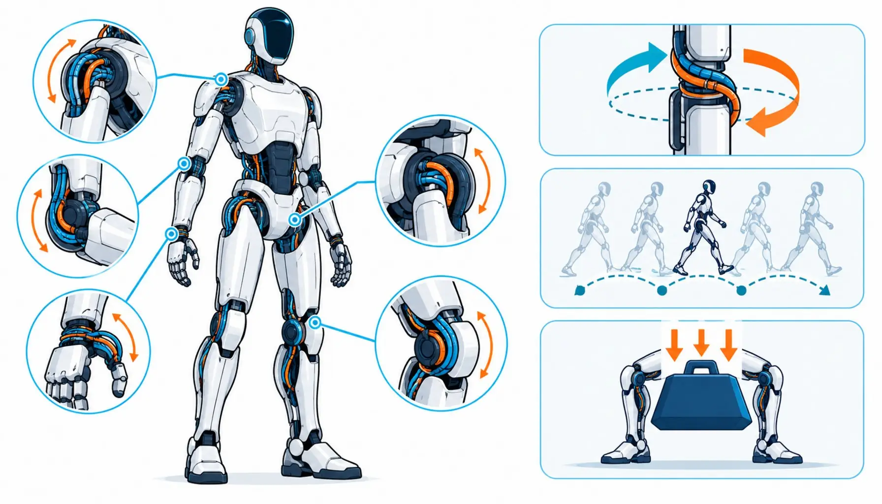
Quick Answer: A humanoid robot packs over thirty actuated joints into a walking body, so its cabling must survive tight radii, torsion at every joint and a brutal weight budget all at once.
No machine category has moved faster in the last two years than the humanoid robot. Unitree alone shipped more than 5,500 humanoid units in 2025 and China accounts for roughly 80 percent of global production, while Tesla, Figure, Agility and a crowd of well-funded startups race toward mass production in 2026. Factories that never touched robotics are now piloting humanoids on real lines. And inside every one of these machines sits a problem that gets almost no press coverage: the wiring. A humanoid is not a robot arm with legs attached. It is a cable-dense bundle of more than thirty actuated joints, distributed batteries, tendon-style transmissions and sensory skin, all packed into a body that has to walk, lift and balance without melting its own harness. This guide is for the engineers, integrators and buyers moving into that world. It explains why humanoid wiring breaks the assumptions of conventional robot cabling, what the routing actually looks like inside an arm or a hip, which specifications separate a harness that survives a million gait cycles from one that fails in week three, and where the honest limits of current practice sit.
Introduction
The best way to understand humanoid cable requirements is to compare the machine to what came before. An industrial six-axis arm routes its dress pack outside the structure, in open air, where bend radii are generous and a failed cable can be swapped in minutes. A humanoid buries its equivalent cabling inside limbs barely wider than the cables themselves. Every joint the robot flexes is a bend the cable must survive; every rotation is torsion the cable must distribute; every gram of harness is a gram stolen from payload or battery life. None of this is theoretical. The general physics of why moving cables fail is covered in the common causes of cable failure, and humanoids concentrate every one of those causes into the smallest volume the industry has ever asked a production harness to occupy. Suppliers able to service that volume are vetted the same way any motion cable partner is, per the manufacturer verification checklist; the sections below walk through the machine joint by joint, then translate the geometry into the specification language a cable buyer can actually use.
Why a Humanoid Is Harder Than an Industrial Arm
Count the actuators first. A typical full-size humanoid carries between thirty and forty actuated degrees of freedom: six or more per arm, several per leg for balance, waist articulation, neck, and active or semi-active hands. An industrial robot arm asks its harness to handle six. Each additional joint is an additional flex zone, and unlike the arm’s wrist, humanoid joints are small. A shoulder might accommodate a cable loop of 80 to 100 millimeters radius; a wrist or ankle joint might allow 30 to 40. Cable rated for flexing at 100 millimeters does not simply flex at 30. The stranding class, the lay length, the jacket thickness and the shield construction all have to be re-engineered for the tighter world, which is the same physics behind ultra-fine conductor classes in any motion application. Then add torsion. Legs rotate during gait; arms rotate during manipulation; heads yaw. A cable passing through a rotating joint accumulates twist with every cycle, and twist is the failure mode that no amount of bending endurance fixes. The constructions that survive it, with long-lay layers and anti-twist geometry, are covered in the dedicated discussion of torsion cable construction. Finally, weight. A humanoid harness might total several hundred meters of wire. At typical motion-cable build densities that can mean kilograms, and kilograms on a walking robot are paid for directly out of battery runtime or payload rating. Thin-wall insulation, lighter jacket compounds and high-strength center elements exist precisely for this trade, and they change the specification conversation from desktop to humanoid in ways most catalogs never mention.
The Routing Reality: Tendons, Hollow Joints and the Cable Backbone
Walk through an arm. The shoulder houses the largest joint motors, and the cables serving the elbow and wrist typically run through or alongside the upper-arm structure, looping over the elbow joint, then continuing down the forearm to the wrist. Where the design uses tendon-driven transmission, the cable competes for space with the tendons themselves, often sharing a narrow channel with no room for a service loop. The wrist is the worst case in the machine: it bends, it rotates, and the hand’s sensing and actuation wiring has to get through it. Some designs use hollow-joint routing, passing the cable through the center of the joint axis, where torsion exposure is highest but the bend loop is protected. Others route around the joint, gaining bend radius but losing it again whenever the limb curls. Either way, the cable at the wrist sees combined bending and twisting at small radii, at high cycle counts, in a package that must stay thin enough for the joint to close. The same story repeats at the hip and knee, where gait cycles add a few hundred thousand flex events per year even for a robot that only works one shift. And none of this accounts for the data backbone: cameras in the head, force sensors at the fingertips, IMUs in the torso, all feeding a central computer over buses that are just as motion-loaded as the power wiring. The table below maps the main cable systems in a humanoid to their duty and the specification that governs each.
| Cable System | Route Through the Machine | Duty Profile | What the Specification Must Capture |
|---|---|---|---|
| Battery and main power | Torso spine, distribution to limb bus bars | High current, low flex count, vibration from gait | Current density in thin-wall build, vibration-rated terminations |
| Joint motor power | Across shoulder, elbow, hip, knee, ankle joints | High flex and torsion at small radii, gait cycle counts | Ultra-fine stranding, torsion balance, tested radius at joint geometry |
| Encoder and sensing | Alongside joint power through the same joints | Same flex duty as power, plus EMI exposure | Shield durability under flex, pair geometry retention, separable routing |
| Hand and fingertip | Through wrist into palm and digits | Smallest radii in the machine, combined bend and twist | Sub-40 mm radius rating, jacket abrasion resistance, minimal diameter |
| Data backbone | Head cameras, torso IMU, limb controllers to compute | Mixed flex and stationary segments, high bandwidth | Flex-rated data construction, bend-stable impedance, connector retention |
The Numbers: What Gait Cycles and Joint Motion Actually Impose
The industry learned to talk about drag chain cable in millions of cycles, and those numbers translate to humanoids with a twist. A humanoid working a warehouse shift walks continuously, and every step loads the leg harness. Half a million gait cycles a year is a conservative estimate for single-shift duty, which means a two-year service life already demands flex performance in the same class as a chain-rated industrial cable. The arm and hand joints cycle less often per hour than a pick-and-place wrist, but they cycle through wider combined motions, mixing bending with rotation in ways that test torsion balance rather than pure flex endurance. And the failure stakes are different. When a drag chain cable fails, a machine stops and a technician swaps the cable. When a humanoid’s wrist cable fails, the robot is down wherever it stood, access may require partial disassembly of the limb, and the swap might take a day instead of an hour. That asymmetry is why humanoid programs are pushing cable validation away from datasheet numbers and toward joint-level testing: the cable flexed in the actual geometry it will occupy, at the actual radius the joint allows, through cycle counts that match real duty. Buyers evaluating suppliers for humanoid programs should ask for exactly that evidence, in the same spirit as the honest reading of flex-life specifications, because the gap between a catalog number and joint-geometry test data is where most programs discover their schedule risk.
Materials and the Weight Budget
Every material choice in a humanoid harness is a trade against grams. Thin-wall insulation saves mass but demands better abrasion resistance, because the jacket is doing less work per millimeter. Ultra-fine, high-flexibility conductor stranding saves bending stress but costs copper fill and DC resistance, so the power circuit sizing gets tighter. Aramid or high-strength center elements carry tensile load without steel’s weight, and they matter more in a humanoid than in almost any other machine, because limb cables get tensioned every time the joint reaches full travel. Jacket compounds have to flex cold, resist the oils and cleaning agents of real facilities, and stay smooth in channels that share space with tendons and structural members. None of these choices is exotic by cable-industry standards; what is new is asking a single build to satisfy all of them at once, inside a diameter budget set by a joint that was designed before anyone consulted the harness engineer. That last point deserves emphasis, because it is the most common failure of humanoid programs so far. Cable requirements discovered after the limb is designed end in compromises that no manufacturer can engineer away. The programs making progress are the ones that bring cable specification into the joint design loop, with the same seriousness that automotive programs brought wiring harness reviews into body design two decades ago.
| Specification Line | Why It Matters for Humanoids | Evidence to Require |
|---|---|---|
| Rated bend radius at joint geometry | Wrist and ankle joints allow 30-40 mm, far below standard motion ratings | Cycle test data at the actual radius, not at 10x diameter |
| Torsion rating in degrees per meter | Legs and wrists rotate continuously; twist accumulates over gait | Combined bend-plus-twist test at joint duty |
| Conductor class and lay length | Fine short-lay stranding is the only class that survives sub-40 mm flexing | Stranding class stated, lay length measured, bending data attached |
| Weight per meter in the final build | Every harness gram costs battery runtime or payload | Verified mass, not catalog estimate, in the thin-wall build |
| Shield durability under flex | Sensing noise at joints reads as balance and control faults | Shield continuity after the full flex cycle count |
| Jacket chemistry and friction | Channels are shared with tendons and structure; facilities are oily | Agent resistance list and friction data against channel materials |
| Service and repair strategy | Limb disassembly for a cable swap costs a shift, not an hour | Modular harness breaks, documented access points, spare strategy |
When Humanoid Cable Rules Are Not the Answer
Honesty about scope matters in a field moving this fast. Much of the humanoid cable conversation today is inherited from industrial motion cable, and that inheritance is mostly sound: the physics of flexing copper does not change because the machine has legs. But some current practice deserves skepticism. Cycle counts extrapolated from chain testing do not automatically describe combined bend-and-twist duty at a wrist, and no industry standard yet defines humanoid harness qualification the way existing standards define chain cable. Programs should treat vendor claims as hypotheses to be tested in their own joint geometry, not as settled evidence, and the reading discipline for that evidence is the same one that governs any honest review of equipment datasheets. The field is also young enough that weight, serviceability and cost trade-offs are being re-litigated in every design cycle, and a specification that made sense twelve months ago may already be obsolete. None of this argues against the machine category; it argues for the same engineering humility the early electric-vehicle harness programs had to adopt. Specify carefully, test in geometry, log every failure, and the wiring will mature at the pace the rest of the robot already has.
RFQ Checklist: Sourcing Cable for a Humanoid Program
Bring these points into the conversation before quotes come back:
- Joint geometry per route: radius, twist per cycle and cycle count, from the CAD model not from assumption
- Required test evidence: flex cycling at actual radius, combined torsion duty, shield continuity after test
- Weight and diameter budgets per limb segment, with tolerance the joint design can absorb
- Material constraints: jacket chemistry against facility agents, cold flex if logistics include unheated spaces
- Connector and termination plan, since terminations fail before cables in most small-joint builds, and the gland and strain-relief hardware around them deserves the same scrutiny, per the cable accessories checklist
- Modularity and service strategy: where the harness breaks apart, and what a swap takes in time
- Traceability and revision control, because humanoid programs iterate fast enough to orphan parts
Conclusion
The humanoid robot is the most cable-dense machine the consumer-facing side of automation has ever produced, and its wiring is a genuine engineering frontier rather than a catalog order. More than thirty actuated joints, tendon-sharing channels, wrist radii under 40 millimeters and a weight budget that taxes every gram: these demands exceed what standard motion cable was designed for, and the programs that respect that gap are the ones whose robots keep walking. The good news is that the underlying physics is known, the material toolkit exists, and the testing discipline is a matter of insisting on evidence in geometry.
Kexingyu Cable Group (KXYE) follows the humanoid segment closely and supplies the motion cable constructions its harnesses draw on: ultra-fine stranding, torsion-balanced builds, aramid-supported cores and thin-wall jackets tested in real duty. For engineering teams defining a harness for a humanoid or any compact multi-joint machine, send the joint geometry and duty profile through the RFQ page, and we will respond with constructions, data and the honest limits of what current builds can do.


