
Isolation Transformers: What They Protect Against and When You Need One
A practical guide to electrical noise, galvanic isolation, medical and drive applications, specification checkpoints, and procurement decisions
Introduction
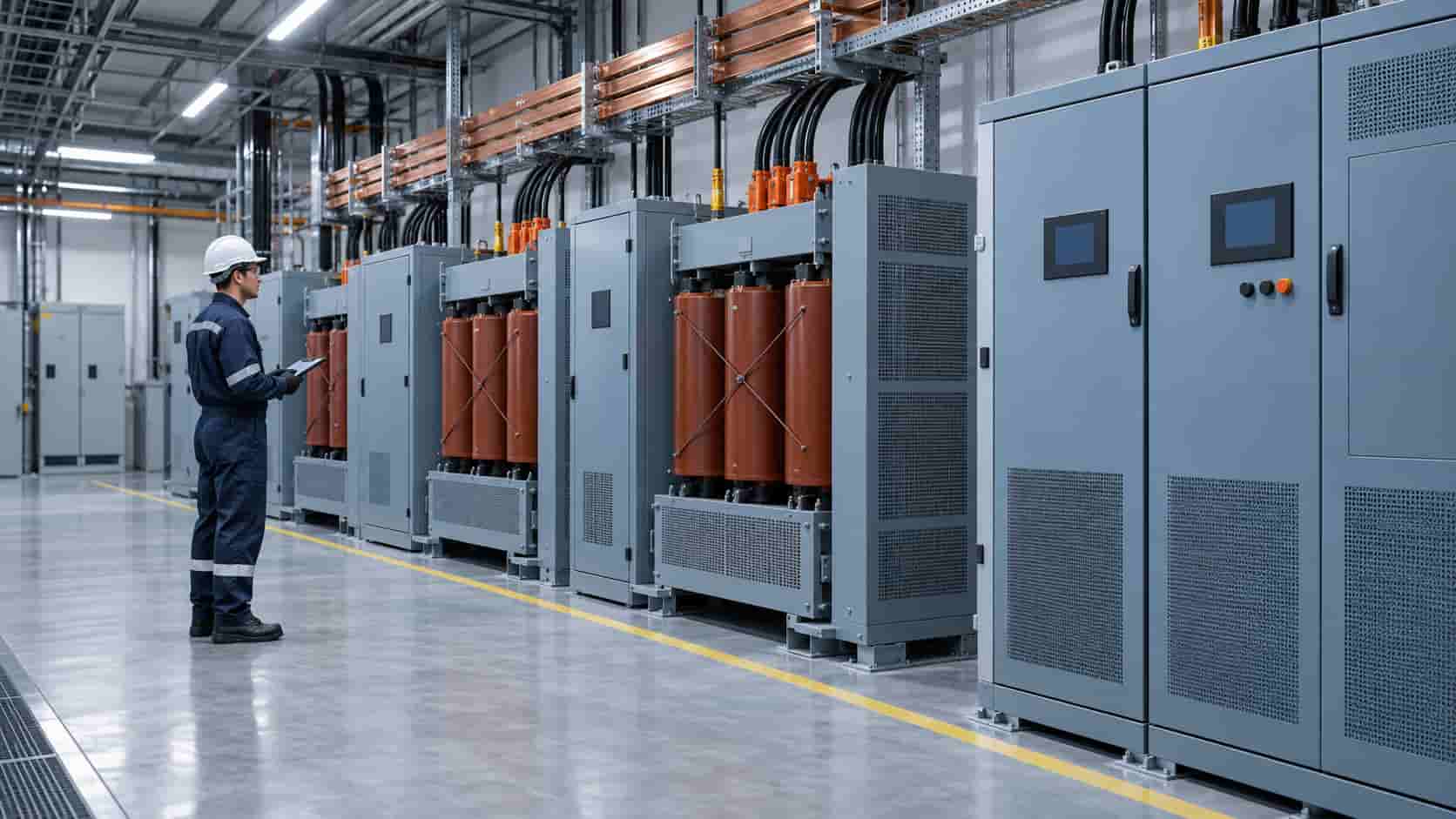
An isolation transformer transfers power between two magnetically coupled windings with no conductive connection between the input and output circuits. In its most useful form it also carries an electrostatic shield between those windings and a design focused on noise attenuation—not only on voltage transformation.
Buyers usually meet this product in one of two situations. Either sensitive equipment keeps misbehaving—nuisance trips, measurement drift, unexplained resets—despite a supply that looks correct on paper, or a specification for a medical, data center or drive application calls for a “separately derived source” and nobody on the project wants to guess what that means for the transformer order.
This guide explains what an isolation transformer actually protects against, where it earns its cost, where it does not, and what to verify before you place an order. The decision should follow the disturbance you need to control—not the assumption that one expensive component fixes every power quality problem. If you are still mapping out the wider equipment scope, start from our complete transformer and substation range, then come back to this page with a clearer picture of where isolation fits.
What Is an Isolation Transformer?
Every two-winding transformer—primary and secondary wound around a shared core—is galvanically isolated by physics: energy crosses the magnetic field, not a wire. When procurement documents say “isolation transformer”, however, they normally mean a purpose-designed unit that goes further:
- An electrostatic (Faraday) shield—a grounded foil or mesh layer between the primary and secondary windings that intercepts high-frequency noise and diverts it to ground instead of letting it couple capacitively across.
- Reduced inter-winding capacitance, achieved through winding geometry and insulation layout, which is what actually determines how well high-frequency disturbances are blocked.
- Thermal margins for non-sinusoidal loadsin K-rated or drive isolation designs, where the winding must survive harmonic currents that would overheat a standard transformer.
The contrast case is the autotransformer: a single winding with taps, electrically shared between input and output. Autotransformers are cheaper, smaller and more efficient for simple ratio changes, but they provide no galvanic separation, no ground-loop control and no meaningful noise attenuation. If a quotation for an “isolation transformer” is dramatically cheaper than the rest, check whether it is actually an autotransformer or an unshielded two-winding unit.
A standard distribution transformer sits in between. It isolates, but its winding layout and capacitance were optimized for cost and efficiency at 50/60 Hz—not for blocking the kilohertz and megahertz content that disturbs modern electronics.
What Does an Isolation Transformer Protect Against?
The value of the product comes from four distinct mechanisms. Knowing which one your project actually needs is the difference between a justified purchase and an expensive ornament.
Common-mode and switching noise
Variable frequency drives, inverters, switching power supplies and modern lighting all inject high-frequency noise onto the supply. Much of it is common-mode—appearing equally on line and neutral relative to ground—which passes through an ordinary transformer almost unchanged. The grounded shield gives that current a short path to earth and sharply reduces what reaches the secondary. Sensitive measurement, control and IT equipment stops seeing disturbances it was never designed to reject.
Ground loops and the separately derived source
A shielded isolation transformer lets you create a new, locally grounded power system: the secondary winding (or its neutral point) is bonded to local earth, independent of the upstream system. This breaks the ground loops that cause hum in analog signals, random faults in RCD-protected circuits and reference-voltage errors between pieces of equipment. In North American practice this is the “separately derived system”; in IEC-based projects it is the reasoning behind dedicated medical and technical power supplies. The principle is the same: give the sensitive system its own clean voltage reference.
Harmonic heating from drives and rectifiers
Six-pulse drive front ends and other rectifier loads draw non-sinusoidal currents that heat windings through skin effect and eddy losses far more than the RMS reading suggests. Drive isolation transformers and K-rated units are built for this duty: stronger coils, upgraded cooling ducts and core margins sized for harmonic content. A standard transformer feeding the same load may run hot, degrade insulation early or trip on spurious overtemperature.
Fault current limitation
The impedance of the transformer limits the fault current available downstream. A deliberately specified impedance—higher than a commodity distribution unit—gives protective devices an easier job and reduces mechanical stress on the secondary installation. This is a real benefit, but it comes with a voltage-drop trade-off under motor starting and peak loads, so the value belongs in the specification, not in a datasheet footnote.
Just as important is what an isolation transformer does not protect against:
- Voltage sags, swells and outages—there is no stored energy in the unit; ride-through requires a UPS or a generator.
- High-energy lightning and switching surges—surge protective devices (SPDs) handle that energy; a shield only trims high-frequency content.
- Frequency conversion—a 50/60 Hz isolation transformer cannot create 400 Hz aircraft power or DC; that requires a converter.
- Power factor or voltage regulation—no tap changer, no capacitors, no stabilization loop.
Isolation Transformer vs Distribution Transformer vs Autotransformer
The three products overlap on the shelf and in marketing language, so align the comparison on what changes for your installation:
| Aspect | Shielded Isolation Transformer | Standard Distribution Transformer | Autotransformer |
|---|---|---|---|
| Galvanic separation | Full, with grounded shield between windings | Full, but unshielded | None—shared winding section |
| High-frequency noise attenuation | Strong; specified common-mode and transverse-mode performance | Limited; winding capacitance not controlled | Effectively none |
| Neutral and grounding flexibility | Secondary can be bonded locally as a separately derived source | Possible, but secondary design not optimized for it | Not available |
| Harmonic load duty | Available as K-rated or drive duty design | Needs derating on rectifier loads | Unsuitable for significant rectifier duty |
| Relative cost, size and losses | Highest of the three | Baseline | Lowest—cheaper copper and core for the same ratio change |
| Typical use | Medical, IT, instrumentation, drive supply, ground-loop correction | General voltage transformation in the network | Ratio correction, motor starting, simple conversion |
Isolation Transformer Use Case 1: Medical and Healthcare Facilities
Operating theatres, imaging suites and intensive-care areas combine strict safety rules with equipment that is exquisitely sensitive to reference quality. IEC-based medical-location standards expect an IT (isolated) supply with local bonding for patient-connected circuits, and imaging modality vendors routinely specify dedicated transformers for MRI, CT and X-ray rooms—both for the separately derived reference and for the harmonic content of the loads. A shielded isolation transformer, often dry-type and installed close to the department, provides that foundation.
The conditions for success are strict: leakage-current limits, monitoring of the isolated system, qualified installation and testing per the applicable medical standard. Isolation helps the power quality problem; it does not replace the medical-location compliance work around it.
Isolation Transformer Use Case 2: Data Centers and IT Rooms
Data halls mix UPS outputs, bypass paths, mechanical loads and dense switching supplies on shared infrastructure. An isolation transformer is used in three typical positions: upstream of sensitive loads to establish a clean, locally referenced supply; on UPS bypass and maintenance paths so the load sees the same reference in every supply mode; and on mechanical or house loads to keep their disturbances away from the IT bus. Where harmonic current is significant—older rectifier front ends, dense VFDs on pumps and CRAC units—K-rated designs prevent the winding-heating problems that standard units develop.
The conditions for success: coordinate the grounding scheme with the UPS and the building earthing design, and confirm efficiency expectations—an extra transformation stage is a permanent loss in the energy budget, so its noise and grounding benefits must be worth that cost.
Isolation Transformer Use Case 3: Industrial Plants with VFDs and DC Drives
Drive-heavy plants—pumping stations, hoists, extrusion lines, rolling mills—concentrate exactly the harmonic currents that isolation and drive-duty transformers are built to survive. Placing a drive isolation transformer at the drive group supply does three jobs at once: it feeds the rectifier with a defined impedance that reduces notching and commutation disturbance on the plant bus, it absorbs harmonic heating without premature aging, and its shield keeps drive-generated noise from spreading back into control and instrumentation circuits.
The conditions for success: the transformer must be sized for the real current spectrum, not just the kW rating, and the plant should still consider harmonic mitigation (chokes, filters, multi-pulse arrangements) as a system question. Isolation is part of the answer—not the whole answer.
Isolation Transformer Use Case 4: Legacy Buildings, Laboratories and Test Benches
Older buildings and growing laboratories accumulate grounding arrangements nobody drew on a single diagram. The symptoms are familiar: audio or measurement channels that hum when one device plugs in, RCDs that trip when equipment is connected across two circuits, data loggers that read differently depending on which socket they use. A shielded isolation transformer with a fresh local neutral-ground bond gives the sensitive system its own reference and removes the loop.
The conditions for success: somebody must map which circuits move to the isolated supply, and the new system must be labeled, tested and documented so the next renovation does not quietly undo it. This is usually a small transformer with an outsized effect—if the diagnosis is correct.
Isolation Transformer Use Case Decision Table
Use the table to align the disturbance, the mechanism and the alternative before committing budget:
Isolation Transformer Use Cases: Conditions and Alternatives
| Use Case | Why Isolation Helps | Conditions for Success | When to Consider an Alternative |
|---|---|---|---|
| Medical and imaging rooms | Separately derived, low-noise supply for patient-connected and diagnostic equipment | Compliance work per the applicable medical-location standard, system monitoring, dry-type unit close to the department | A dedicated standard transformer may suffice where no medical-location rules apply |
| Data centers and IT rooms | Clean local reference; identical grounding across UPS and bypass paths; harmonic-tolerant windings | Grounding scheme coordinated with UPS design; efficiency cost of the extra stage accepted | UPS with built-in isolation or a distribution transformer may meet the requirement at lower loss |
| VFD and DC drive supply | Defined impedance, harmonic-rated windings, shielded noise containment | Correct sizing for the actual current spectrum; plant-wide harmonic strategy in place | Line reactors or multi-pulse arrangements may be enough for small drive groups |
| Labs, test benches, legacy buildings | Breaks ground loops; gives instruments and analyzers a clean reference | Circuit scope mapped; new system labeled, tested and documented | Re-cabling or dedicated circuits may solve the loop at lower cost |
| Generator and remote sites | Defined system reference regardless of generator bonding; noise attenuation | Generator bonding confirmed; non-linear loads accounted for in sizing | A properly specified distribution transformer may suffice when no noise issue exists |
When an Isolation Transformer Is Not the Answer
The honest section. An isolation transformer is the wrong tool when the problem is energy, not noise: brownouts, outages and voltage swells pass straight through, so if the complaint is “equipment restarts when the grid blinks”, the specification you need is a UPS, not a transformer. Surge damage calls for coordinated SPDs. Low power factor calls for capacitor banks or filters. Chronic undervoltage calls for tap optimization or voltage regulation upstream.
It is also the wrong tool when a less expensive component already does the job. A standard two-winding distribution transformer provides galvanic separation; if nobody can articulate which high-frequency disturbance, ground loop or harmonic duty the shield is supposed to handle, the isolation specification is being bought as insurance rather than engineering. And on sites where no power quality survey has been done at all, ordering an isolation transformer first is a guess—one that can easily be confirmed or eliminated by a day of measurement before the order is placed.
Key Specifications to Check Before You Order
Once the use case is confirmed, the quotation becomes a specification exercise. These are the checkpoints that decide whether the delivered unit performs the way the project assumed:
- Rating and sizing.Establish demand, growth margin and—critically for drive and medical loads—the real current spectrum. Sizing by nameplate kW alone is the most common sizing error; the transformer capacity sizing method applies here in full.
- Voltages, ratio and taps.Primary and secondary voltage, frequency, and tap range (typically ±2 × 2.5%) matched to the actual site voltage, not the nominal one.
- Stated as a value, not “standard”—it sets fault limitation and voltage drop under starting and peak loads.
- Insulation class and temperature rise.For dry-type units typically class F or H insulation with 75 K, 100 K or 125 K rise—cooler rise means margin and longer life.
- Shield configuration.Single or double electrostatic shield, grounding arrangement, and an inter-winding capacitance figure in the datasheet—not just the word “shielded”.
- Harmonic duty.K-factor rating or an explicit statement of the design current spectrum for rectifier-fed loads.
- Dry-type or oil-immersed.Indoor, medical and IT locations favor dry-type (VPI or cast resin); outdoor and higher ratings may justify oil units with their containment requirements. The trade-offs are set out in our oil-immersed vs dry-type comparison.
- Enclosure and environment.IP rating, indoor/outdoor duty, altitude above 1,000 m derating, ambient extremes, corrosive or dusty atmospheres, and seismic requirements where they apply.
- Standards and tests.IEC 60076 series governs design and routine testing (ratio, polarity and winding resistance, insulation resistance, applied and induced voltage tests); North American projects may reference UL/CSA listings. Witness points and test reports should be named in the purchase order.
Ordering from a Manufacturer: What to Verify
Isolation performance is invisible on arrival—you are buying winding discipline, insulation quality and test integrity, so the manufacturer matters as much as the datasheet. Before ordering, verify the factory’s routine test capability and reports, the makes of core steel, conductor, insulation and components, and the packing plan for export transport. A factory audit or third-party inspection before shipment is cheap compared with a shield that was never properly earthed or a winding that fails its induced voltage test after a season of drive duty. The verification checklist in our transformer manufacturer due diligence guide transfers directly to isolation units.
What to Include in an Isolation Transformer RFQ
A complete request saves a round of clarification and gets comparable quotations:
- Single-line diagram extract showing where the unit sits and how the secondary is to be grounded
- Primary/secondary voltage, frequency and required ratio or step
- Rated kVA plus load types, expected growth and duty cycle
- Harmonic information: current spectrum or K-factor requirement for rectifier loads
- Shield requirement (single/double, grounding arrangement) and any capacitance or attenuation expectation
- Impedance range, tap range, insulation class and temperature rise
- Dry-type or oil-immersed preference with enclosure, IP and environmental conditions (altitude, ambient, corrosive atmosphere)
- Applicable standards, required routine and type tests, witnessed FAT scope
- Documentation package, spare parts, delivery date and Incoterms
Conclusion
An isolation transformer earns its cost in four specific ways: attenuating high-frequency common-mode noise with a grounded shield, creating a separately derived and locally referenced supply, surviving harmonic-rich drive and rectifier duty, and limiting fault current with deliberate impedance. Medical rooms, data halls, drive-heavy plants, laboratories and generator-fed sites all have a genuine use case for it.
The discipline is to name the disturbance before naming the component. Where the problem is energy—sags, outages, surges—other equipment belongs in the specification. Where the problem is noise, grounding or harmonic duty, specify the shield, the impedance, the thermal design and the tests explicitly, and buy the transformer from a manufacturer who can prove all four. Compare quotations on that basis—not on the size of the discount.
Recent Posts
Energy Storage for Data Centers: A Growing Backup Power Option
Energy Storage for Data Centers: A Growing Backup Power Option Batteries have always backed up data centers in the form of UPS strings. Grid-scale BESS
Thermal Runaway in Lithium Batteries: What BESS Buyers Should Understand
Thermal Runaway in Lithium Batteries: What BESS Buyers Should Understand How thermal runaway starts, how it propagates, and which evidence buyers should require before approving
Switchgear Lead Times in 2026: A Buyer’s Planning Guide
Switchgear Lead Times in 2026: A Buyer’s Planning Guide Realistic timelines vary significantly by voltage class and type — here’s how to plan procurement without