Site Earthing and RCD Protection: Making Cable and Devices Work Together
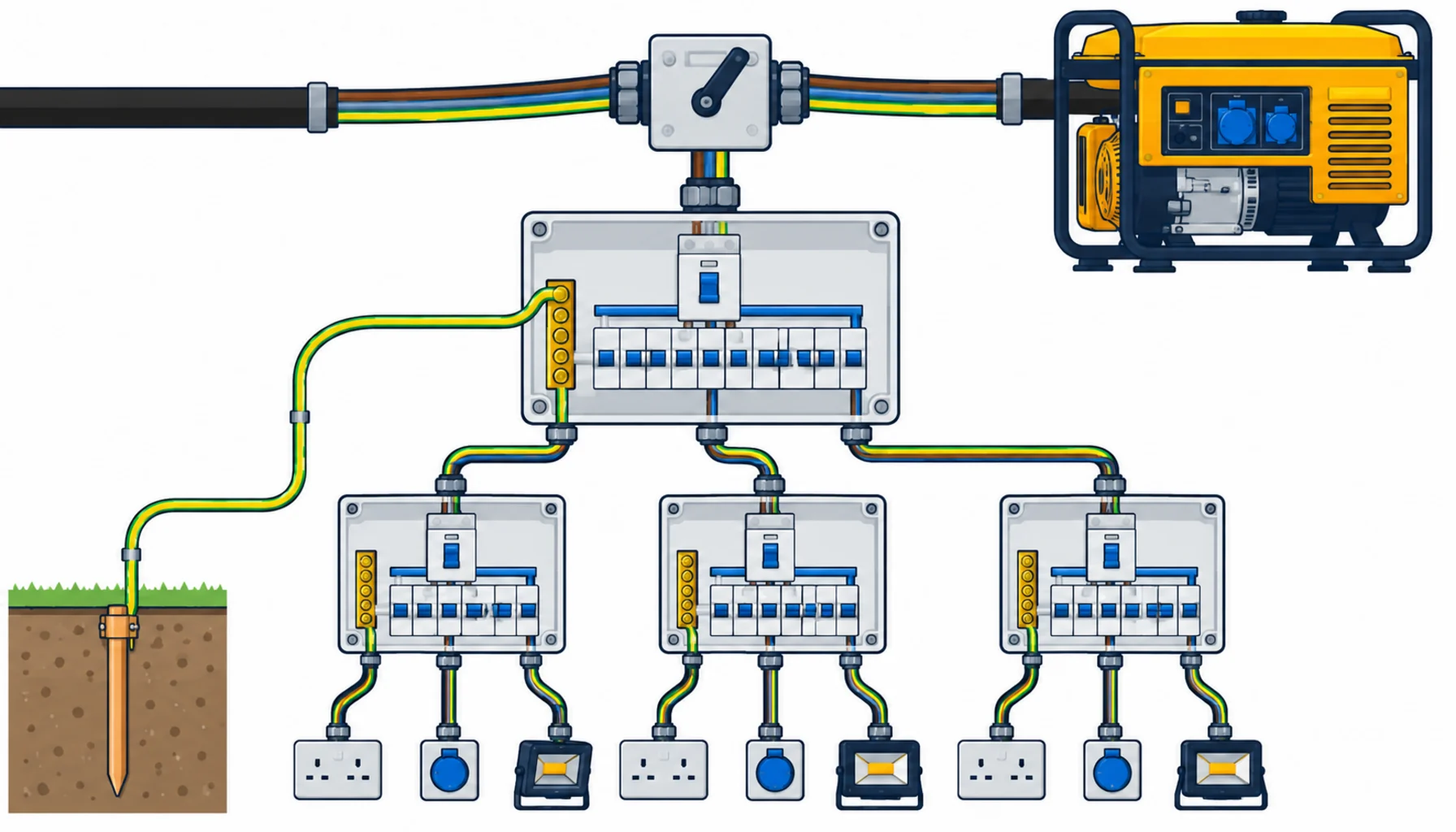
Quick Answer: On a construction site, earthing and RCD protection are one system: the earthing arrangement sets what fault current can flow, the RCDs catch what earthing cannot, and the cable between them decides whether either works. Buy the supply arrangement as a decision first, grade the RCDs so a fault trips the nearest device, size protective conductors on the same discipline as the lives they protect, and test the whole chain at installation and on a schedule.
Introduction
Construction sites are the most hostile electrical environment most people will ever touch: wet ground, steelwork everywhere, temporary connections made and remade weekly, and the public walking past. The protective system is the only thing between a fault and a fatality, and it is bought as three separate line items that have to work as one.
The buying task is coordination. An RCD that never trips because the earth path is missing is a decorative box. An earth electrode that cannot clear a fault on its own needs the RCD to do the job. This guide covers the supply arrangement decision, RCD grading, the conductors that tie it together, and the tests that prove the chain works.
Start With the Supply Arrangement
Everything else follows from how the site takes power. Where the supply comes from the public network, the arrangement is usually a converted TN system with the supplier’s earth not reliable on site, which pushes most contractors to a TT-style arrangement: a site electrode system, and RCD protection on everything, because the earth loop impedance is too high to clear faults fast on fuses alone.
Where the site runs on generators, the decision is cleaner and more often got wrong. A generator creates its own neutral-earth relationship, and getting it wrong produces either an installation that cannot trip or one that trips everything. Generator sites need a deliberate bonding arrangement, switching that does not break the earth reference between supplies, and RCDs sized to the actual arrangement; our note on generator ATS cable connections covers the changeover wiring that keeps the earth path intact when supplies swap.
State the arrangement in the electrical package before anything is bought, because the distribution boxes, the RCD types and the conductor sizes all depend on it. Retrofitting an arrangement is one of the most expensive errors a site electrical package can make.
RCD Grading: Trips That Find the Fault
A site with one big RCD at the head trips everything for every fault, and crews respond by defeating it. The workable arrangement grades protection in levels: a time-delayed or selective device at the head, sensitive 30 milliamp protection at the point of use, and intermediate devices sized so the nearest breaker to a fault is the one that trips.
What to buy. The head device needs selectivity features, not just a rating. The final circuits need genuine 30 milliamp devices with the breaking capacity for the site supply, and the intermediate boxes need devices matched to the downstream count. Our three-level construction distribution box is built around exactly this graded arrangement, with the levels matched at the factory rather than assembled ad hoc on site.
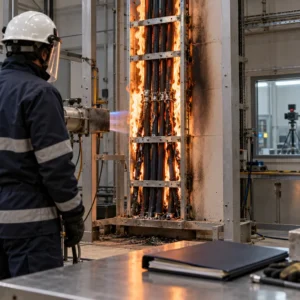
Test buttons are not tests. Every RCD has a button that proves the mechanism moves; only an injected test current proves the device trips at its rated residual current and time. The site schedule should include periodic RCD testing with records, because devices left untested fail silently, and the failure is only discovered by the fault that does not clear.
Bonding the Structures the Site Builds
Around the distribution system, the site builds conductive structures that need deliberate bonding: site cabins, scaffolding that grows a metre a day, hoist masts, tower crane bases and the metal formwork that ends up everywhere. Each is a conductive mass in a wet environment, and each either joins the protective system deliberately or joins it by accident.
The buying task is a bonding schedule with the hardware to match: bonds sized to the arrangement, clamps that grip without damaging the structure, and testable joints at positions the crew can actually reach. Tower cranes and hoists deserve particular attention because they combine height, lightning exposure and the public boundary; their earthing belongs in the erection specification, not in an improvisation at height. Site cabins need bonding at each relocation, which makes the clamp and lug standard part of the moving checklist.
Scaffolding is the classic argument. Full bonding of every tube is impractical and mostly unnecessary, but the arrangements that apply, and the points where scaffolding approaches exposed electrical equipment, are decisions for the electrical package rather than the scaffolding crew. Write them down, buy the hardware against the schedule, and re-verify after every major reconfiguration. Sites that leave bonding to chance pay for it in the fault that uses the scaffolding as its return path, discovered by whoever is holding the scaffold at the time.
The Conductors That Tie It Together
The protective system is only as good as the copper connecting it, and site conductors live a harder life than any permanent installation.
Protective conductors. Earth continuity from every distribution box to the electrode system, and from every item of plant to its supply, needs conductor sized on the arrangement’s fault requirements and protected mechanically. The green-yellow core of the supply cable usually carries the return path, which means the supply cable’s construction matters beyond its current rating; where runs are exposed to damage, mechanically protected or armoured construction earns its cost, and our note on armoured versus unarmoured cable covers where the line sits.
Conductor quality. Continuity depends on the copper being real copper, correctly stranded and correctly terminated. Conductor classes and their flexing behaviour are standardised, and our note on IEC 60228 conductor classes explains the classes; the point for site procurement is that Class 5 and 6 flexible conductors terminate differently from solid cores, and a termination standard that ignores the class produces the high-resistance joints that quietly disable the earth path.
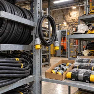
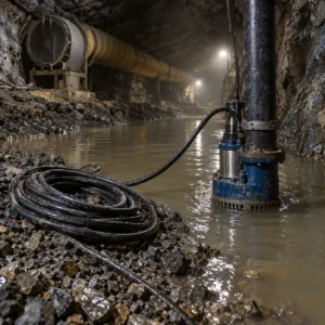
The flexible supply cable itself. Site supply cable to tools and temporary boards is handled, dragged and soaked, and its sheath and core construction should be specified for that duty; our H07RN-F splash-resistant rubber cable is the standard heavy-duty site construction, and it is worth insisting on the genuine article rather than a lookalike, because the earth core inside it is the conductor the RCD depends on.
| Component | Role in the Chain | What to Specify | Evidence to Demand | Cost and Lead-Time Driver | How It Fails |
|---|---|---|---|---|---|
| Electrode system | Sets the earth reference and fault path | Electrode count and depth per soil condition, clamped and labelled connections, testable joints | Earth resistance measurement record at installation | Cheap hardware; installation access drives cost | Corroded clamps, built-over electrodes, unmeasured resistance |
| Head and intermediate RCDs | Grade the trip so the nearest device clears | Selective head device, rated breaking capacity, levels matched to downstream count | Trip current and time test records, selectivity declaration | Graded boxes cost more than single devices and stop defeat culture | Silent failure, nuisance tripping from bad grading, defeat by crew |
| Final 30 mA RCDs | Personal protection at the point of use | Genuine 30 mA devices on every final circuit, weather-rated enclosures | Injected test current records per device | Modest unit cost; testing labour is the real spend | Untested devices that fail closed, single devices protecting everything |
| Protective conductors and supply cable | Carry the fault current that makes protection work | Sized protective conductor, armoured or protected runs, genuine flexible site cable with sound earth core | Continuity measurements per run, conductor class declaration | Copper content plus mechanical protection | High-resistance joints, damaged earth cores, continuity lost unnoticed |
Generators, Changeover and the Earth Reference
Most sites run dual supply at some point: mains while available, generator for outages and early works, and the changeover is where earthing arrangements die. A changeover that switches line conductors but leaves two neutrals bonded to two different earth references creates an installation where RCD behaviour is unpredictable, and the crew discovers it the way crews discover everything.
The buying answer is to purchase the changeover as a system: the switching device, the neutral-earth bonding arrangement, and the cable connections specified together, with the earth path continuity through the changeover stated on the drawing. Sites that buy generators, ATS units and distribution boxes from separate suppliers inherit the coordination problem themselves; buying the package together pushes it back to the supplier, and our note on coordinated power equipment supply covers what that responsibility transfer looks like. The same logic applies to the earthing accessories: bonds, clamps and earth bars are cheap items that fail expensively, and they belong in the main order with certificates rather than in the site consumables bin.
Testing and Records: Proving the Chain
The protective chain is a chain of invisible properties: earth resistance, loop impedance, trip current and time, and continuity. None of them can be seen, and all of them decay. The site’s testing regime is therefore part of the procurement, not an afterthought.
At installation. Earth resistance measured and recorded, continuity of every protective conductor verified, RCD trip current and time injected and recorded, and insulation resistance of the new runs measured before energisation; our note on insulation resistance testing covers the method. The handover record is the baseline every later test compares against.
On a schedule. RCD tests on a fixed cycle with dated records per device, earth resistance rechecked seasonally where soil conditions change, and continuity re-verified after any modification. Sites without records retest nothing, and the protective system decays into a set of assumptions. The records also answer the question every contractor eventually faces after an incident: was the protection working, and can you prove it?
What to Freeze Before the Order
| Decision | What to State | Evidence to Attach | Cost of Leaving It Open |
|---|---|---|---|
| Supply arrangement | TT or converted TN, generator bonding, changeover scheme | A single-line diagram naming the arrangement | Retrofit of the most expensive decision in the package |
| RCD grading | Selective head, intermediate levels, 30 mA at point of use | Grading declaration per distribution level | Everything-trips heads and a crew that defeats them |
| Protective conductor sizing | Conductor sizes per the arrangement's fault requirements | Sizing notes and continuity records | An earth path that cannot clear the faults it exists for |
| Supply cable construction | Genuine flexible site cable, protected runs at damage points | Conductor class declaration and cable certificates | Lookalike cable with the properties the RCD depends on removed |
| Testing regime | Installation records plus a dated test cycle | Handover test sheet as the baseline | Silent decay discovered by the fault that does not clear |
| Package responsibility | Generators, ATS, boxes and cable bought as one system | Supplier coordination named in the contract | The changeover coordination problem inherited by the site |
When a Site Earthing Specification Is Not the Answer
When the soil defeats the electrode. High-resistance ground sometimes needs deeper electrodes, multiple rods or a plate arrangement, not bigger RCDs. Measure first, then buy copper.
When the fault is the defeat culture. If crews bypass protection because grading is bad, the fix is the grading, and no amount of better hardware stops a defeated device.
When the tool is the hazard. A tool with damaged insulation trips a healthy RCD repeatedly; the RCD is doing its job. Replace the tool, not the protection.
When the site needs a designed network. Large sites with cranes, hoists and instrumentation deserve an earthing design with calculated values, not an assembled arrangement; bring the designer in before the order.
RFQ Checklist
- Single-line diagram naming the supply arrangement and bonding
- Generator changeover scheme with earth path continuity stated
- RCD grading table per distribution level, 30 mA at point of use
- Breaking capacity and selectivity declarations per device
- Protective conductor sizing notes and construction class
- Genuine flexible site cable with certificates, protected at damage points
- Electrode system design with testable joints
- Installation test record template: earth, continuity, RCD, insulation
- Dated retest cycle with records per device
- Earthing accessories certificated in the main order, not the consumables bin
- Bonding schedule for cranes, hoists and site cabins, re-verified at each move
Conclusion
Site earthing and RCD protection work as one chain, and the chain is bought, not assumed: the supply arrangement first, graded devices second, conductors sized and protected third, the site’s own structures bonded deliberately, and a testing regime that keeps records instead of memories. Freeze those decisions before the order, and the site’s protective system does its work invisibly, which is the only way protective work should show up.
Kexingyu Cable Group (KXYE) has manufactured cable in Quanzhou since 1996, supplying genuine flexible site cable, protective conductor constructions and coordinated distribution equipment for construction projects, with certificates against every delivery and test support through installation. Send us your supply arrangement and site plan, and we will come back with the constructions, the grading and the coordination. The fastest route is a request for quotation.