
Buying Zero-Downtime Power Tie-Ins for Live Data Halls: Hardware, Method and What to Verify
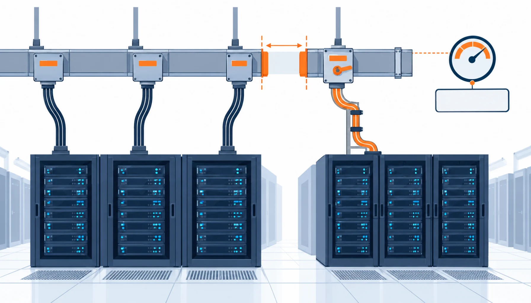
Quick Answer: A tie-in without downtime is decided by two purchases made earlier: an isolation point that can be worked on while the run stays live, and a spare way in the board the new row will be fed from. Where those exist, the energization is a short planned operation with a written method statement. Where they do not, the tie-in becomes a shutdown or a live connection that few organisations will authorise. Specify the isolation at busway order stage and the spare ways at switchboard order stage, and the expansion you plan for next year can be done without one.
Growth in a data hall is rarely a single project. It arrives as rows, a few racks at a time, each one needing power from equipment that has been running for years. The tie-in is where that meets reality.
Introduction
Expansion work is usually planned around the load and the racks, and the electrical connection is treated as a detail to be resolved on site. In practice the connection point decides the schedule, the risk and the cost, and it is fixed long before anyone asks about it. A hall built with isolating tap-offs and spare ways can be extended on a Tuesday morning. A hall built without them needs a window that the tenant has to approve.
Our note on fault isolation and bypass strategies covers the equipment that makes isolation possible, and our note on maintenance windows in 24/7 facilities covers the fallback when it is not. This note is about the tie-in itself: where the new row comes from, what the method statement has to say, and what has to be proved before and after the row is energised.
Where a New Row Can Actually Be Fed From
Four connection points are available in a live hall, and each constrains the work in a different way.
A spare way in an existing board. The cheapest and simplest option, provided the board was ordered with spare ways and space. The work is confined to one compartment, and the rest of the board stays in service. Without spares, this option does not exist.
An isolating tap-off on an existing busway run. The tie-in happens at the tap-off rather than at the origin, so the new row can be fed from a run that serves other rows without disturbing them. This is the option that most expansions depend on and the one most often lost by ordering non-isolating tap-offs.
A new board fed from a spare compartment upstream. Where the existing board has no capacity, the new board is fed from a spare compartment at the upstream switchboard. This adds a cable route and a terminator to the scope but keeps the work at an accessible boundary.
A live connection to an energised busbar. Rarely justified and increasingly discouraged. It requires a permit regime, insulated tooling, arc rated protection and a plan for what happens if the connection is not completed. Treat it as an exception to be avoided by design rather than a method to be specified.
The Decision Table: Tie-In Points Compared
The table prices the four points against what each one requires to be available.
| Tie-In Point | What to Specify | Evidence You Should Receive | Cost and Window Shape | Failure Mode If Chosen Wrong |
|---|---|---|---|---|
| Spare way in an existing board | Spare way count and rating at order stage, compartment space, cabling route left available | Board single line diagram with spares marked, and an as-built showing the spare route | Lowest cost; work confined to one compartment with no effect on other ways | No spare ways, so the new row triggers a board change or a shutdown |
| Isolating tap-off on a live busway | Isolating plug-in design, rating, keying schedule, shutters, and a tap-off register | Type tests, keying schedule, and a tap-off register mapped to rows | Premium on the busway order; tie-in is a short local operation | Non-isolating tap-offs, which force the whole run down for one new row |
| New board from a spare upstream compartment | Spare compartment rating, cable route and support, termination method, protection settings | Spare compartment record, route drawing, and a protection coordination study | Adds cable and termination cost; keeps the work at an accessible boundary | Protection settings left uncoordinated, so the new board trips the existing one |
| Live connection to an energised busbar | Permit regime, insulated tooling, arc rated protection, abort and completion criteria | Approved method statement, permit record, and supervision sign off | No equipment cost, highest risk and the least predictable duration | An incident with no isolation path and no way to make the connection safe quickly |
The Method Statement Is Part of What You Buy
Energization work in a live hall is defined by documents as much as by hardware, and those documents should be commissioned with the same attention as the equipment.
The switching sequence. Written step by step, from the isolation of the tie-in point to the point at which the new row can be loaded, with the state of every affected device at each step. Where a sequence exists, the operation becomes a checklist. Where it does not, it becomes a discussion at the board.
The abort criteria. The conditions under which the work stops. Insulation resistance below the criterion, a temperature rise during a load test, a protection relay that behaves unexpectedly, or a schedule that has run past the agreed tolerance. Both the abort condition and the authority to call it belong in writing, and the authority should sit with someone who is present.
The temporary arrangements. Where existing circuits are temporarily re-fed or where a bypass is in use, the temporary state, its duration and the compensating measures go into the statement. Temporary arrangements that outlive the project are the most common source of undocumented risk in a growing hall.
The records. Every tie-in should end with an updated single line diagram, an updated tap-off register, a test record and an entry in the asset register, dated. Where the records are updated only at the end of a project, the hall carries a period in which nobody can say what is connected to what.
What to Freeze Before the Tie-In Order
| Item | What to State | Evidence to Attach | Cost of Leaving It Open |
|---|---|---|---|
| Tie-in point | The exact device and compartment the new row will be fed from, named on the drawing | A marked up single line diagram issued with the tender | A connection decided on site from what is accessible rather than from what is suitable |
| Spare ways and compartments | How many, at what rating, and how the spare cable route reaches them | Board drawings with spares and route shown | A tie-in that requires a new board or a shutdown window |
| Tap-off isolation | Isolating plug-in units specified for the busway runs that may be extended later | Type tests and a keying schedule | Whole runs shut down for the sake of one new row |
| Protection coordination | Protection settings and discrimination for the new board against the existing upstream device | A coordination study covering the expanded configuration | A new board that trips the existing one, converting a growth project into an outage |
| Cable route and support | The route, support spacing, fire stopping and the penetration register entry | Route drawing and penetration register | A tie-in cable run through an unsealed penetration, discovered at handover |
| Method statement | The switching sequence, abort criteria, temporary arrangements and the named authority to abort | Approved method statement and permit | Work stopped halfway with no agreed way to finish or reverse it |
| Test and acceptance criteria | Insulation and continuity criteria, the load test level, and the acceptance record format | Test plan with criteria stated numerically | A row energised on a visual check, with no record that it was proved |
| Record updates | Which documents are updated after the tie-in, in what format, and within what period | Agreed record set and a named owner | A hall where the drawings lag the installation by months |
When a Live Tie-In Is Not the Answer
Where the load can tolerate a short interruption. If the new row is being built for a tenant who is not yet live, and the existing rows can tolerate a brief interruption of a non-critical feed, a planned short outage is cheaper and safer than any live working. Live tie-ins are justified by the cost of downtime, so verify that cost before choosing one.
Where the protection study has not been done. Adding a load to an existing system changes the fault level and the discrimination. Where the study has not been updated, the energization transfers risk to every circuit on the board, not just the new one.
Where the records are already unreliable. A tie-in performed against drawings that do not match the installation is a live working operation with imperfect information. Fix the records first; on most sites the survey needed to do that is a fraction of the cost of a live working incident.
Where the expansion is really a rebuild. Where more than a small proportion of the board capacity is being added, the honest answer is that the board needs replacing, and no tie-in method changes that. Our note on data center expansion cabling covers how to tell the two cases apart.
RFQ Checklist
- Tie-in point named on the drawing at tender stage, not left to site
- Spare ways and spare compartments listed with ratings and route access
- Isolating plug-in tap-offs specified for any busway run that may be extended
- Protection coordination study updated for the expanded configuration before energization
- Cable route, support, fire stopping and penetration register entry included in the scope
- Method statement required as a deliverable, with the switching sequence and abort criteria
- Named individual with authority to abort stated in the method statement
- Temporary arrangements listed with duration and compensating measures
- Insulation and continuity criteria, plus a load test level, stated numerically
- Load test performed at a representative load with results recorded per circuit
- Updated single line diagram, tap-off register and asset register entries as handover deliverables
- Record update period stated, with a named owner for each document
Conclusion
Zero-downtime expansion is designed at the beginning rather than achieved at the end. The spare way, the isolating tap-off and the coordination study are all decisions taken when the original equipment was ordered, and all of them are cheap then and expensive later. A hall that was built with them can grow on a normal working day, which is worth more than the premium they cost.
Kexingyu Cable Group (KXYE) supplies the equipment a tie-in depends on, including the WDZ-YJY, WDZN-YJY, BTTZ, NG-A (BTLY), KVV and YJV ranges, the busbar tap-off box that makes an isolating connection to a live run possible, and the GGD power distribution cabinet that the new row can be fed from, from one factory group with copper price linkage on project-scale orders. Send the tie-in point you intend to use and the spare capacity you have, and we will return the equipment ratings and factory test records that the method statement needs; the fastest route is a request for quotation.


