
Switchgear Manufacturer China: What to Verify Before You Order
Switchgear carries a higher stakes verification checklist than most equipment categories — here's what to confirm before you commit to an order.
An Inverter Alarm Is Not Always an Inverter Failure
An inverter sits between several systems: the PV array or other DC source, the utility or local AC network, batteries where fitted, communications, protection equipment, and the surrounding environment. A shutdown reported by the inverter may originate in any one of them.
For example, low insulation resistance may come from damaged PV cable or wet connectors, an overvoltage alarm may be caused by the local grid, and reduced output may simply reflect high temperature, shading, or an active power limit. Replacing the inverter without confirming the root cause can leave the original problem unresolved.
The first task is therefore to record the exact alarm code, operating state, time, weather, grid conditions, load, DC voltage and current, and recent site work. Compare this evidence with the manual for the exact model and firmware version.
Safety Comes Before Troubleshooting
Solar and battery inverters can remain connected to hazardous DC voltage even after the AC supply is switched off. Internal capacitors may also retain charge. Only qualified personnel using the manufacturer’s isolation procedure and appropriate test equipment should open enclosures or perform electrical measurements.
Do not repeatedly reset an inverter that shows smoke, a burning smell, unusual heat, water ingress, damaged connectors, arcing marks, loose parts, or repeated protection trips. Isolate the equipment as the approved site procedure requires, keep personnel clear, and escalate to the responsible technician or manufacturer.
Remote fault codes and visual checks can guide the response, but they do not replace lockout, verification of isolation, personal protective equipment, and the electrical-safety rules applicable at the site.
1. Overtemperature and Thermal Derating
High internal temperature may cause power derating, intermittent shutdown, accelerated ageing, or permanent component damage. Common contributors include direct sunlight, high ambient temperature, blocked airflow, dust on heat sinks, failed fans, insufficient enclosure ventilation, altitude derating, and operation near the inverter’s limits for long periods.
Check the recorded temperature and derating history, installation clearance, air path, fan condition, filter condition where used, and ambient temperature. Cleaning must follow the manufacturer’s method; compressed air, liquids, or opening the enclosure may be prohibited.
Prevention begins during design. Select the mounting location, sun protection, room ventilation, enclosure arrangement, and inverter rating from the worst expected ambient conditions and the manufacturer’s derating curves—not only the nominal power rating.
2. Cooling-Fan Failure
Fan-cooled inverters depend on the fan assembly to maintain safe component temperature. Bearings wear, blades accumulate dust, filters block, connectors loosen, and fan-speed feedback can fail. Warning signs include unusual noise, frequent thermal derating, a fan alarm, or one fan running differently from the others.
Fans are service parts on many products, but replacement intervals and procedures vary. Use approved parts with the correct airflow, voltage, connector, direction, and environmental rating. Replacing a fan without removing the contamination or airflow restriction that caused the problem may produce another early failure.
3. Capacitor and Power-Electronic Ageing
DC-link capacitors, power semiconductors, relays, contactors, and other internal components experience thermal and electrical stress throughout operation. Electrolytic-capacitor life is particularly sensitive to temperature, ripple current, and voltage, but it is not possible to diagnose capacitor condition reliably from age alone.
Possible symptoms include unstable DC-link behavior, difficulty starting, ripple-related alarms, reduced power, repeated internal faults, or visible swelling discovered during authorized service. These symptoms can have other causes, so internal diagnosis should be performed by trained service personnel.
Good thermal design, operation within voltage and current limits, clean cooling paths, controlled component substitutions, and manufacturer-defined service intervals reduce risk. For critical sites, consider planned replacement or refurbishment based on duty, environment, condition data, and support availability.
4. DC Overvoltage, Undervoltage, or Overcurrent
DC input faults can result from incorrect string length, temperature-dependent open-circuit voltage, loose or reversed connections, excessive parallel-string current, incompatible modules, battery-voltage mismatch, or faults in the DC wiring. Cold weather can raise PV open-circuit voltage, while high module temperature can push operating voltage below the useful MPPT range.
Verify the approved design against the exact module, string schedule, site temperature range, MPPT limits, maximum DC voltage, operating current, and short-circuit-current rating. Our inverter sizing guide and MPPT guide explain why voltage and current checks must be performed separately.
Never disconnect DC connectors under load unless the equipment and procedure explicitly permit it. Damaged, mismatched, poorly crimped, or incompletely engaged connectors can overheat or arc and should be handled by qualified personnel.
5. Insulation Resistance and Ground-Fault Alarms
Low insulation resistance may be caused by damaged cable insulation, trapped moisture, contaminated connectors, crushed wiring, a module fault, an incorrectly installed surge device, or leakage elsewhere in the DC circuit. The alarm is a protective response and should not be bypassed.
Use string-level isolation and insulation testing only under an approved procedure with suitable instruments and compatible voltage limits. Conditions can change with rain, dew, or temperature, so the time and weather associated with the alarm are useful diagnostic evidence.
Prevention includes correct cable routing, bend radius, mechanical protection, compatible connectors, controlled crimping, sealed cable entries, drainage, and inspection after construction or roof work.
6. Grid Voltage, Frequency, and Power-Quality Trips
A grid-connected inverter must disconnect or change operation when voltage, frequency, anti-islanding, or other protection limits are violated. Repeated trips may indicate a weak grid, incorrect settings, undersized AC cable, high local voltage caused by export, generator instability, loose connections, or a utility disturbance rather than an internal defect.
Record voltage and frequency at the inverter and at the point of connection under different power levels. Review conductor size, voltage rise, transformer taps, protection settings, grid profile, phase balance, and utility requirements. Grid-protection windows should never be widened simply to suppress alarms without authorization.
Sites that require power during outages need the correct system architecture. Our guide to inverters for unstable grid regions explains why standard grid-tied units, hybrid backup outputs, generators, and batteries behave differently.
7. Surge and Lightning Damage
Nearby lightning, direct lightning exposure, utility switching, inductive-load switching, and long cable runs can introduce transient overvoltage on DC, AC, or communication circuits. Damage may be immediate or may weaken components and cause later failure.
Protection requires a coordinated system: suitable surge-protection devices, correct type and voltage rating, short connection paths, bonding, earthing, lightning-protection coordination where applicable, and replacement indicators or remote contacts. Installing one SPD beside the inverter does not compensate for poor conductor routing or an inadequate earthing system.
After a significant event, inspect the whole protection path and connected equipment. Replacing only the inverter may leave failed SPDs or damaged cables in service.
8. Moisture, Dust, Corrosion, and Pest Ingress
An enclosure rating applies only when the product is installed as specified with correct glands, connectors, seals, covers, orientation, and maintenance. Damaged gaskets, unused openings, condensation, salt mist, conductive dust, insects, and rodents can all compromise reliability.
Look for external corrosion, damaged cable entries, water tracks, blocked drains or vents, dust buildup, and evidence of pests without opening energized equipment. Coastal, mining, agricultural, and high-humidity locations may require more than a nominal IP rating, including corrosion-resistant materials, filtered rooms, heaters, or environmental control.
Do not pressure-wash an inverter or use unapproved solvents. Inspection and cleaning intervals should reflect the actual site environment rather than a generic annual schedule.
9. Communication, Metering, and Firmware Problems
Loss of monitoring does not always mean loss of power conversion. Faults may arise from network settings, cable polarity, termination resistors, duplicate addresses, failed gateways, weak cellular service, incompatible meters, time synchronization, cloud outages, or changed passwords.
Separate local inverter operation from remote-platform status. Check local indicators, event logs, meter direction, communication topology, power supplies, and approved configuration. Keep a record of IP addresses, device addresses, firmware versions, parameter files, and commissioning credentials under appropriate access control.
Firmware should be updated only through an approved process. Confirm compatibility, release notes, backup settings, authorization, and recovery procedure. An unnecessary or interrupted update can create new faults, while outdated firmware may retain known issues.
10. Incorrect Settings or Commissioning Errors
Wrong grid profile, time, export limit, current-transformer direction, battery protocol, phase sequence, power factor, protection threshold, or operating mode can produce trips or poor performance that resembles hardware failure.
Commissioning should use an approved checklist and capture the final parameter set, firmware, serial numbers, test results, photos, and sign-offs. Changes after commissioning should be controlled and documented so a future technician can understand why a setting differs from the factory default.
11. Loose Connections and Installation Defects
Incorrect torque, poor crimping, incompatible connectors, damaged conductors, inadequate strain relief, wrong cable size, and contamination at terminals can create resistance, heating, intermittent faults, and arcing. Thermal cycling may worsen a marginal connection over time.
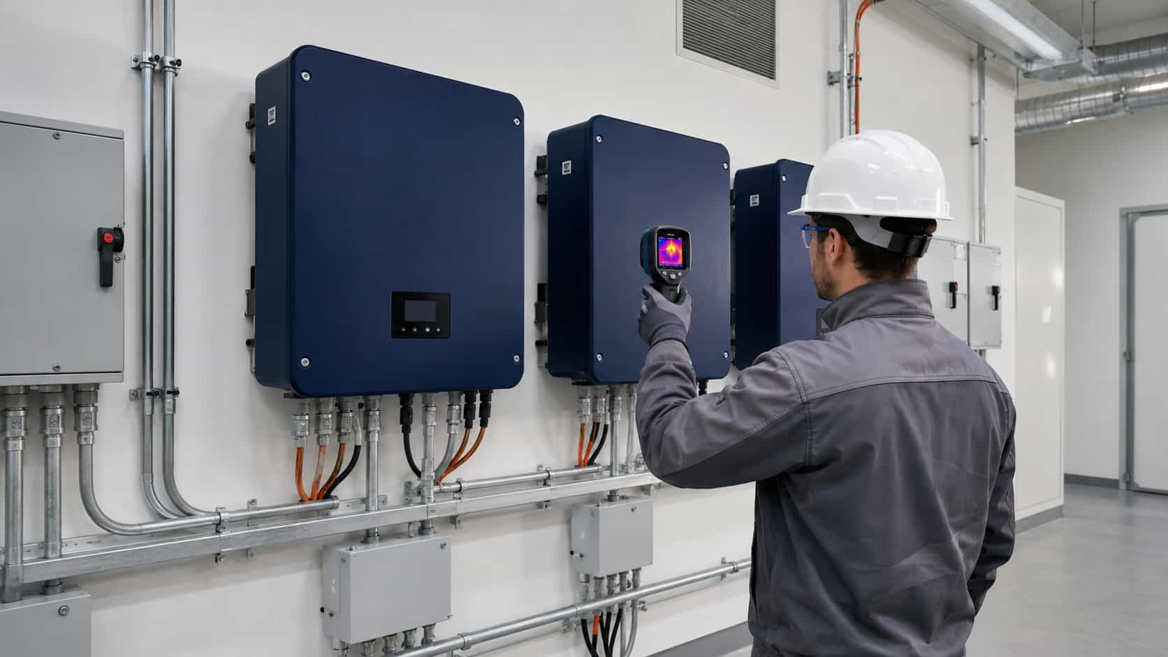
Connections should be installed with specified tools and torque values, then inspected under the project quality plan. Thermal imaging under stable load can help identify abnormal temperature differences, but interpretation requires comparable loading, emissivity awareness, and safe access.
Do not retighten terminals indiscriminately. Some connections require replacement, preparation, or a defined retorque procedure, and work must be performed in the isolated state.
12. Oversizing, Clipping, and Persistent Overload
DC oversizing is common and can be acceptable within the manufacturer’s design limits. Clipping on high-production periods is not itself a failure. Problems arise when voltage, per-MPPT current, short-circuit current, thermal conditions, AC loading, or battery power exceed permitted limits.
Persistent operation at high output in a hot environment can increase thermal stress even when no immediate trip occurs. Model expected energy, clipping, ambient derating, reactive-power requirements, and future array changes before final selection.
Correct sizing reduces avoidable stress, but excessive oversizing is not automatically economical. Use project-specific simulations and the exact inverter data rather than a universal DC/AC ratio.
| Fault symptom | Possible causes | Safe first checks | Escalate when |
|---|---|---|---|
| Overtemperature or derating | High ambient temperature, blocked airflow, dust or fan failure | Review temperature logs, clearances and external airflow path | Fan alarm repeats or abnormal heat remains |
| Low insulation resistance | Wet connectors, damaged cable, module fault or contaminated DC circuit | Record weather and identify affected string using approved procedures | Fault persists or electrical testing is required |
| Grid voltage/frequency trip | Utility disturbance, voltage rise, cable drop, wrong profile or loose connection | Review event logs and measured point-of-connection conditions | Trips repeat or settings require changes |
| DC overvoltage or overcurrent | Incorrect string design, cold voltage, excess parallel current or wiring fault | Compare approved string schedule with model limits | Measurements or DC disconnection are required |
| Monitoring offline | Network, gateway, address, power supply, meter or cloud issue | Confirm whether local power conversion continues and review communications | Local alarms, firmware or protected settings are involved |
| Burning smell, smoke or arcing marks | Loose connection, damaged component, ingress or severe electrical fault | Keep personnel clear and follow the approved isolation procedure | Immediately—do not repeatedly reset or open the unit |
A Preventive Maintenance Program That Finds Problems Early
A useful maintenance plan combines remote monitoring with scheduled site inspection. Review alarms, availability, power trends, temperature, fan operation, insulation behavior, grid events, communication quality, and changes between comparable strings or units.
On site, inspect mounting, clearances, enclosure condition, cable support, connectors, glands, corrosion, contamination, ventilation, fans, filters, surge-device indicators, earthing and external signs of overheating. The permitted scope depends on the equipment and technician authorization.
Maintain serial-number records, firmware and parameter backups, test reports, cleaning history, replaced parts, photos, and warranty correspondence. Trend data is often more valuable than one measurement because gradual degradation can be identified before an outage.
When to Contact the Manufacturer
Escalate when an alarm repeats after approved external checks, when internal faults or insulation faults remain unresolved, when the unit shows physical damage or ingress, after a significant surge event, or when firmware, protected settings, warranty parts, or internal service are involved.
Provide the exact model, serial number, firmware, fault code, event-log export, time of occurrence, operating conditions, DC and AC readings collected safely, system diagram, photos, recent changes, and troubleshooting already completed. A complete evidence package shortens diagnosis and reduces unnecessary parts replacement.
Manufacturer selection affects long-term serviceability. The solar inverter manufacturer checklist explains how to verify test records, component control, warranty procedures, spares, firmware support, and international technical response before ordering.
Reliability Starts Before Installation
Most inverter failures cannot be prevented by maintenance alone. Correct sizing, environmental design, surge coordination, cable and connector quality, grid studies, compatible batteries, controlled commissioning, and service planning all begin before the equipment reaches site.
KEXINGYU E-POWER GROUP can review inverter requirements as part of a wider solar, storage, and electrical project. Final maintenance intervals, protection arrangements, allowable measurements, service parts, and troubleshooting steps must always follow the exact model documentation and approved site procedures.


