
Energy Storage PCS Explained: The Bridge Between Battery and Grid
How a power conversion system controls bidirectional energy flow—and which power, voltage, grid, protection, cooling, and communication specifications buyers should verify.
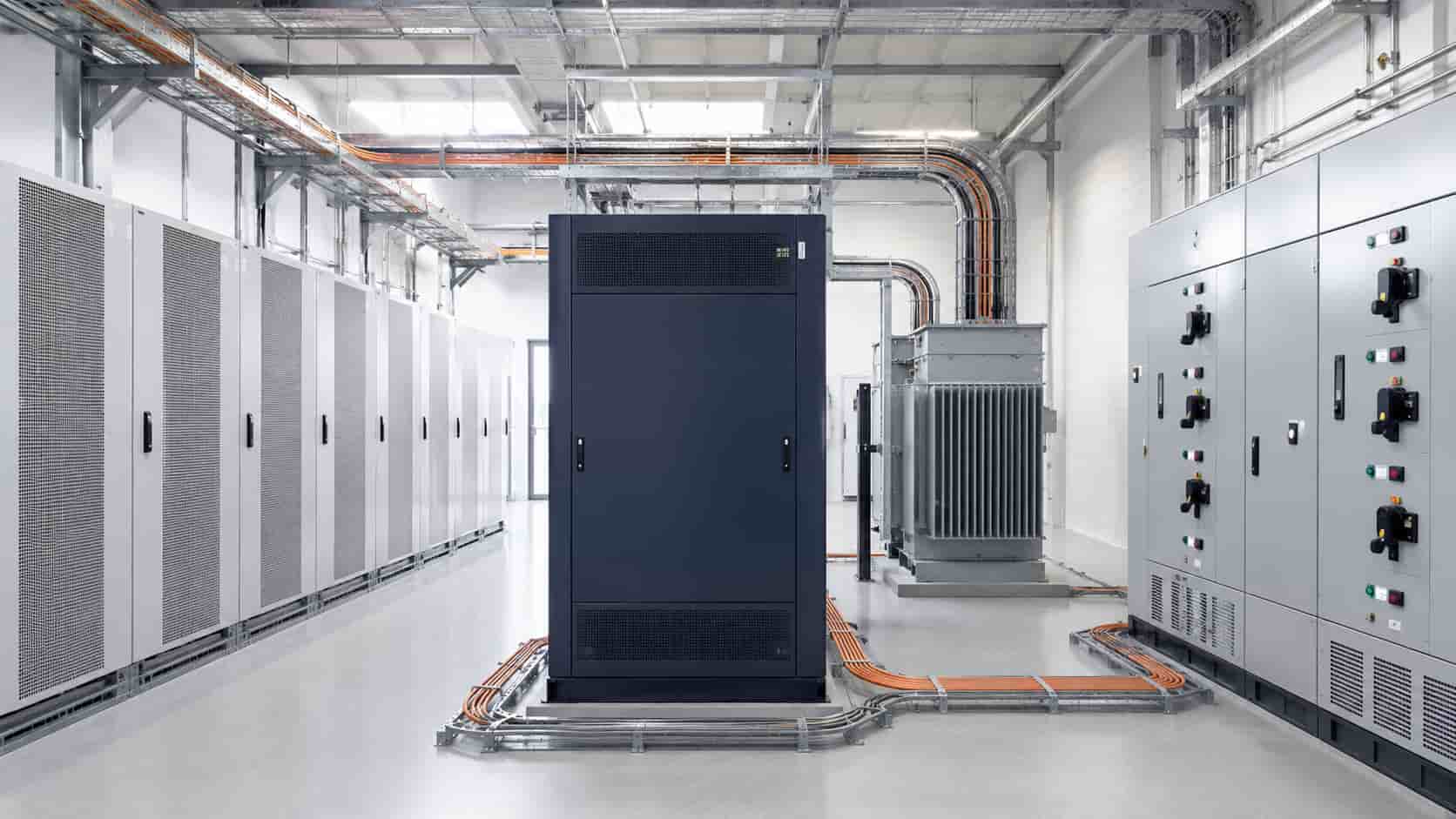
What PCS Means in Energy Storage
PCS stands for power conversion system. In a battery energy storage system (BESS), it is the power-electronic equipment that converts energy between the battery’s DC bus and an AC system such as a facility network, microgrid, generator bus, or utility connection.
During discharge, the PCS converts DC battery energy into controlled AC power. During AC charging, it converts AC power back into DC. It also regulates current, voltage, active power, reactive power, and operating transitions within limits received from the battery and supervisory controls.
The term can describe a single bidirectional inverter, a group of modular converter cabinets, or a larger package containing filters, switchgear, controls, cooling, and auxiliary equipment. Procurement documents should therefore define the PCS boundary instead of assuming that every supplier includes the same components.
How a PCS Differs from a Solar Inverter
A conventional grid-tied PV inverter converts variable DC power from solar modules into AC power. A battery PCS must normally control power in both directions because the battery charges and discharges. However, it is inaccurate to say that every solar inverter is one-way: hybrid and battery inverters may also be bidirectional.
The more useful distinction is the source, control objective, system scale, and certified operating mode. A PV inverter follows the available array power and uses MPPT. A battery PCS follows charge and discharge commands while respecting battery limits. Some products combine PV MPPT inputs, battery conversion, grid connection, and backup output in one hybrid platform.
Our guide to what a solar inverter is explains PV conversion, while the comparison of on-grid, off-grid, and hybrid inverter systems shows how combined architectures differ.
The Main Power Path
On the DC side, the PCS connects to the battery system directly or through DC distribution, contactors, fuses, isolation devices, and sometimes a DC/DC stage. On the AC side, it connects through switchgear and may require a transformer before reaching the facility bus or utility point of connection.
The conversion can use a single-stage or multi-stage topology depending on the battery-voltage range, galvanic-isolation requirements, grid voltage, and product design. The chosen topology influences efficiency, usable DC range, fault behavior, footprint, and the equipment included outside the PCS cabinet.
A single-line diagram should show the battery racks, DC combiner or distribution, PCS modules, AC protection, transformer, auxiliary supply, metering, earthing, communications, and point of connection. Without this diagram, interface gaps are easy to miss.
Charging and Discharging Control
The PCS receives a power command from a local controller or energy management system and translates it into controlled DC current and AC power. During charging, it must remain within battery voltage, current, temperature, state-of-charge, and cell-level limits communicated by the battery management system.
During discharge, it controls active power while maintaining required AC voltage, frequency, current, and power-quality limits. Ramp rate, response time, minimum stable power, overload capability, and transition behavior matter for services such as peak shaving, frequency response, backup, and renewable smoothing.
The PCS does not decide battery safety limits independently. If the BMS reduces the permitted charge or discharge current, the PCS should follow the updated limit. Communication loss behavior must be defined: the system may ramp to zero, hold a restricted output, or stop depending on the approved design.
PCS, BMS, and EMS: Different Responsibilities
The battery management system monitors cells, modules, temperatures, insulation, contactors, state of charge, and safety limits. The PCS performs electrical conversion and AC-side control. The energy management system coordinates the operating objective across the PCS, batteries, meters, PV, generators, loads, and grid interface.
These systems exchange commands, limits, status, alarms, and measurements, but one should not silently assume another’s safety function. The interface schedule should define signal ownership, update rates, units, timeout behavior, fallback state, alarm priorities, time synchronization, and protocol mapping.
Common physical and software interfaces include CAN, Modbus RTU, Modbus TCP, IEC 61850, and vendor-specific protocols. Naming a protocol alone does not prove interoperability; the register map, control sequence, data scaling, and tested firmware combination must match.
Grid-Following and Grid-Forming Operation
A grid-following PCS synchronizes to an established AC voltage and frequency. It is widely used for grid-connected energy storage but normally needs an existing grid or another grid-forming source to establish the waveform.
A grid-forming PCS can establish and regulate voltage and frequency for an islanded network, subject to its control design and system limits. This capability is relevant to microgrids, weak grids, renewable-dominant systems, and restoration strategies, but the label alone is insufficient.
Buyers should verify islanding detection, transition sequence, black-start capability, synchronization and reconnection, load-step response, fault-current behavior, generator coordination, protection philosophy, parallel operation, and stable operation with the intended mix of sources. Black start and seamless transfer are not automatic features of every PCS.
Active Power, Reactive Power, and Power Quality
A PCS may provide active-power control, reactive-power control, power-factor control, voltage support, frequency response, ramp-rate limiting, and other functions. The available combination depends on the converter’s kVA capability and operating point.
If the PCS is already delivering near its maximum active power, less current capacity may remain for reactive power unless it is oversized in kVA. A 1 MW active-power requirement does not necessarily mean a 1 MVA converter is adequate when simultaneous reactive support is required.
Request the P-Q capability curve, power-factor range, performance across voltage and temperature, harmonic current data, flicker information where relevant, and the conditions under which output is derated. Grid-service claims should be tied to the applicable code and test evidence.
PCS vs Hybrid Inverter
The terms overlap because both may connect batteries and AC systems. Hybrid inverter is commonly used for integrated residential and commercial products that combine PV, battery, grid, and backup functions. PCS is more common in commercial, industrial, microgrid, and utility storage projects where the battery converter is specified as a subsystem.
This is a market convention rather than a universal technical definition. A large hybrid platform may provide sophisticated grid services, and a compact PCS may serve a small commercial system. Compare architecture and functions rather than choosing from the product name alone.
Ask whether PV connects directly to the unit, whether solar and battery share an AC bus or DC bus, which equipment controls backup loads, and whether a transformer, transfer switch, grid-protection relay, or external EMS is required.
| Comparison area | Energy storage PCS | Hybrid inverter | Buyer check |
|---|---|---|---|
| Typical role | Dedicated battery-to-AC conversion subsystem | Integrated PV, battery, grid and sometimes backup functions | Define what equipment is included in the product boundary |
| PV connection | Often no direct PV MPPT input in an AC-coupled system | Frequently includes direct PV MPPT inputs | Confirm AC-coupled or DC-coupled architecture |
| System scale | Common in C&I, microgrid and utility BESS projects | Common in residential and smaller commercial systems | Do not select from the product name alone |
| Supervisory control | Often relies on external BMS, EMS and plant controller | More functions may be integrated into one platform | Map signal ownership and communication interfaces |
| Grid support | May offer advanced P-Q control, grid following or grid forming | Capabilities vary widely by product and market | Verify test evidence, operating limits and certifications |
| Black start and backup | Available only on suitable models and system designs | Backup output may be integrated but has defined limits | Confirm transfer, load-step, overload and restart behavior |
Understanding kW, kVA, kWh, and C-Rate
PCS active-power capacity is stated in kilowatts, while apparent-power capability is stated in kilovolt-amperes. Battery energy capacity is stated in kilowatt-hours. Power determines how quickly energy can be moved; energy determines how long a given output can be sustained, subject to usable state of charge, efficiency, temperature, ageing, and battery power limits.
A 1 MW PCS paired with 2 MWh of usable battery energy is often described as a two-hour system at rated power before allowing for operating reserves and losses. The power-to-energy ratio is also related to C-rate: 1 MW applied to 2 MWh corresponds approximately to 0.5C, but the battery manufacturer’s definition and usable capacity basis should be confirmed.
The PCS should not be selected from battery energy alone. Model the maximum charge and discharge power, duration, state-of-charge window, duty cycle, auxiliary consumption, efficiency, reactive-power duty, overload, future degradation, and the application’s dispatch profile.
DC Voltage Range and Battery Compatibility
The battery voltage changes with state of charge, current, temperature, cell chemistry, ageing, and configuration. The complete operating range must stay within the PCS DC window, and the PCS must be able to deliver the required power at the lowest and highest operating voltages without exceeding current limits.
Check maximum DC voltage, minimum operating voltage, startup requirements, continuous and peak current, short-circuit protection, pre-charge sequence, polarity protection, insulation monitoring, DC grounding philosophy, contactor coordination, and allowable cable length.
Battery compatibility also requires a tested BMS interface, matching protection thresholds, agreed alarm handling, and validated charge and discharge limits. A matching nominal voltage is not enough.
Efficiency and Thermal Performance
PCS efficiency varies with load, voltage, power factor, direction of power flow, temperature, and auxiliary consumption. A peak efficiency figure does not predict annual system losses by itself. Request charge and discharge efficiency curves over the intended operating range and identify whether cooling and transformer losses are included.
High ambient temperature, altitude, blocked filters, cooling-system faults, or simultaneous reactive-power duty can reduce available power. Air-cooled and liquid-cooled designs have different infrastructure, maintenance, noise, redundancy, leak-management, and environmental requirements.
Thermal design should account for room heat rejection, HVAC or ventilation, spacing, recirculation, dust, humidity, corrosion, auxiliary power, and loss of a cooling component. The maintenance principles in our common inverter failures guide also apply to PCS equipment.
Protection and Fault Coordination
The PCS must coordinate with battery protection, DC fuses or breakers, AC switchgear, transformer protection, grid relays, earthing, surge protection, fire strategy, emergency shutdown, and site control. Converter current during a fault may be limited and controlled differently from a rotating generator, affecting protection sensitivity and selectivity.
Ask for fault-current contribution and duration in each operating mode, ride-through behavior, anti-islanding, overvoltage and undervoltage protection, frequency protection, overcurrent protection, insulation monitoring, DC arc or ground-fault functions where provided, emergency-stop logic, and safe shutdown sequence.
Protection studies must reflect grid-connected, islanded, generator-supported, charging, discharging, and standby modes. A setting that coordinates in one mode may not coordinate in another.
Modularity, Redundancy, and Availability
Large PCS installations may use multiple converter modules or cabinets. Modularity can allow staged capacity, easier replacement, and partial operation during maintenance, but only if the AC and DC architecture, controls, cooling, and spare-parts strategy support it.
Clarify whether one failed module reduces capacity or shuts down the complete system, whether modules can be isolated safely, how load is shared, and whether maintenance can occur without de-energizing adjacent equipment. N+1 claims should be verified against the required site output, not only the number of installed modules.
Availability planning should include controller redundancy, auxiliary supplies, communication networks, cooling equipment, transformers, switchgear, spares, remote support, firmware management, and mean time to repair.
How to Specify a PCS for Procurement
Provide the application and operating modes, battery chemistry and voltage range, usable energy, maximum charge and discharge power, duration, grid voltage and frequency, transformer arrangement, point-of-connection requirements, fault level, reactive-power duty, grid code, islanding and black-start requirements, ambient conditions, altitude, enclosure, communications, and cybersecurity requirements.
Require the supplier to state continuous kW and kVA ratings, P-Q curve, overload duration, DC current across the voltage range, efficiency curves in both directions, auxiliary consumption, response time, ramp rate, grid-forming capability, fault-current behavior, harmonic performance, derating, cooling, protection, dimensions, weight, noise, standards, and test evidence.
Then define interface documents, models for power-system studies, factory testing, site testing, training, spares, warranty, remote access, firmware support, and performance guarantees. Final selection should use the complete system duty rather than one headline MW rating.
Where KEXINGYU E-POWER GROUP Fits
KEXINGYU E-POWER GROUP can support PCS selection and integration as part of commercial and utility-scale energy storage projects. The final package may include PCS cabinets, battery systems, transformers, switchgear, controls, protection, communications, and prefabricated enclosures depending on project scope.
All claims about grid-forming operation, black start, efficiency, overload, certification, compatibility, and environmental performance should be confirmed against the exact model and approved project documentation before ordering.
Energy Storage PCS Questions
Recent Posts
Switchgear Lead Times in 2026: A Buyer’s Planning Guide
Switchgear Lead Times in 2026: A Buyer’s Planning Guide Realistic timelines vary significantly by voltage class and type — here’s how to plan procurement without
What Is BESS? A Guide to Battery Energy Storage Systems for C&I Buyers
What Is BESS? A Guide to Battery Energy Storage Systems for C&I Buyers A clear explainer on what BESS systems actually are, how the pieces
Switchgear vs Transformer Lead Times: What EPC Contractors Need to Know
Switchgear vs Transformer Lead Times: What EPC Contractors Need to Know A practical breakdown of why these two equipment categories behave differently in procurement, and