
Rectifiers vs Inverters: Understanding AC-DC Power Conversion
A practical guide to conversion direction, circuit topology, performance specifications, and how rectifiers and inverters work together in UPS, VFD, telecom, and energy storage systems.
The Fundamental Difference
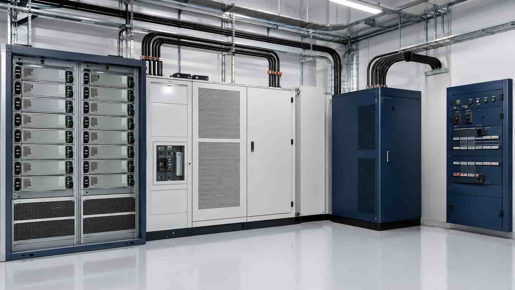
A rectifier converts alternating current (AC) into direct current (DC). An inverter converts DC into AC. These definitions describe the direction of power conversion, but real products often include additional filtering, regulation, isolation, protection, controls, communications, and energy storage.
The source and load determine which function is needed. AC utility power feeding a DC telecom bus requires rectification. A battery supplying an AC load requires inversion. A system that charges a battery from AC and later returns energy to an AC network needs both directions.
Modern bidirectional converters may use the same controlled semiconductor bridge for rectifying and inverting, so the product label does not always reveal its internal topology. Buyers should begin with the required inputs, outputs, operating modes, and power-flow direction.
What Is AC and What Is DC?
AC voltage and current change direction periodically. Utility networks use AC because voltage can be transformed efficiently and distributed through established generation, transmission, and protection systems. Frequency, phase, voltage, power factor, and waveform quality are important AC characteristics.
DC maintains one polarity, although its magnitude and ripple can vary. Batteries, PV modules, electronic circuits, DC control systems, and many communication loads operate internally on DC. DC voltage, current, ripple, regulation, grounding, and fault interruption require separate consideration.
Power conversion does not create energy. Every stage introduces losses and heat. Adding unnecessary AC-DC-AC or DC-AC-DC stages can reduce overall efficiency, increase cost, and add failure points.
How a Rectifier Works
The simplest rectifier uses diodes that conduct automatically according to AC polarity. Single-phase and three-phase diode bridges produce an unregulated DC output whose average voltage depends on the AC input and circuit topology. Capacitors, inductors, or other filters smooth the pulsating output.
A controlled rectifier can use thyristors, also called SCRs, to adjust the conduction point and therefore the DC output. These systems remain common in industrial chargers and legacy DC drives, but their input power factor and harmonic performance must be evaluated.
An active front end uses controlled switches such as IGBTs or MOSFETs with high-speed control. It can regulate the DC bus, improve input current waveform and power factor, and—when designed for it—allow power to flow back toward the AC system.
Rectifier Is a Function, Not Always a Complete Charger
A battery charger contains a rectification function when supplied from AC, but it must also control voltage and current according to the battery chemistry, temperature, state, protection limits, and charging profile. Calling a basic rectifier a battery charger can omit essential battery-management requirements.
Likewise, a telecom rectifier module is normally part of a wider DC power plant containing shelves, controllers, distribution, battery connections, low-voltage disconnects, alarms, and redundancy. The module rating alone does not define the complete system.
For industrial DC systems, buyers should specify nominal and operating DC voltage, regulation, ripple, current limit, battery type, charging modes, distribution, fault level, earthing, alarms, communications, and required autonomy.
Key Rectifier Performance Specifications
Important AC-input specifications include voltage and frequency range, phase configuration, power factor, total harmonic current distortion, inrush current, surge withstand, and compatibility with generators or weak supplies.
On the DC side, check nominal voltage, adjustment range, continuous and overload current, regulation, ripple and noise, current sharing, efficiency, soft start, protection, and behavior during battery connection or load steps.
For modular systems, also verify hot-swap capability, N+1 design, controller redundancy, module derating, cooling, acoustic noise, communications, alarm contacts, and whether one failed module affects the DC bus.
How an Inverter Works
An inverter uses controlled semiconductor switches to connect a DC source to the output in a carefully timed sequence. Pulse-width modulation creates a controlled AC waveform whose voltage, frequency, phase, and current can be regulated. Filters may be used to reduce switching components and produce the required output quality.
The DC source may be a battery, PV array through an MPPT stage, fuel cell, rectified DC link, or another converter. The inverter control strategy depends on the application: it may establish an independent AC supply, synchronize and exchange power with a grid, or generate variable frequency for a motor.
Our guide to what a solar inverter is explains PV applications. The same broad DC-to-AC principle appears in UPS equipment, motor drives, marine power, traction, microgrids, and energy storage.
Three Common Inverter Operating Roles
A stand-alone or grid-forming inverter establishes local AC voltage and frequency for loads. Its important characteristics include waveform quality, load-step response, overload, short-circuit behavior, black start, neutral arrangement, and compatibility with motors, transformers, and nonlinear loads.
A grid-following inverter synchronizes with an existing AC network and controls exported or imported current. Anti-islanding, voltage and frequency response, ride-through, reactive power, active-power control, and grid-code compliance become central.
A motor-drive inverter supplies variable voltage and frequency to control motor speed and torque. The VFD comparison guide explains why output waveform, cable length, motor insulation, control method, braking, and EMC matter in that application.
Key Inverter Performance Specifications
Check the permitted DC voltage and current range, startup behavior, continuous AC kW and kVA, nominal voltage and frequency, phase configuration, efficiency curve, standby consumption, power-factor capability, harmonic performance, overload duration, and environmental derating.
For stand-alone loads, verify voltage regulation, output waveform, transfer behavior, surge capability, load crest factor, motor-start performance, unbalanced-load capability, short-circuit protection, and recovery after overload.
For grid-connected equipment, verify the exact model, firmware, regional profile, certificates, approved-product status, communications, P-Q capability, and project interconnection requirements. A generic statement of “grid compatible” is not sufficient.
Where Rectifiers and Inverters Work Together
Many power systems contain both functions. Their arrangement may use two separate conversion stages, one bidirectional stage, or several coordinated converters depending on isolation, redundancy, efficiency, voltage range, and operating requirements.
Understanding the sequence helps buyers identify every interface. It also reveals conversion losses: the overall efficiency of an AC-DC-AC path is the product of the efficiencies of its stages, with additional losses from transformers, filters, cooling, and auxiliary systems.
Where Rectifiers and Inverters Work Together
Many power systems contain both functions. Their arrangement may use two separate conversion stages, one bidirectional stage, or several coordinated converters depending on isolation, redundancy, efficiency, voltage range, and operating requirements.
Understanding the sequence helps buyers identify every interface. It also reveals conversion losses: the overall efficiency of an AC-DC-AC path is the product of the efficiencies of its stages, with additional losses from transformers, filters, cooling, and auxiliary systems.
| Comparison area | Rectifier | Inverter | Buyer focus |
|---|---|---|---|
| Conversion direction | AC to DC | DC to AC | Confirm whether power must flow in one or both directions |
| Typical sources | Utility AC or generator | Battery, PV, fuel cell or DC link | Specify full input voltage and frequency ranges |
| Typical applications | DC power plant, charger, UPS front end and VFD DC link | AC backup, solar, grid export and motor control | Do not use the product name without defining operating mode |
| Key output metric | DC regulation, ripple and current limit | AC voltage, frequency, waveform and overload | Request performance curves, not only nominal ratings |
| Source-side impact | Power factor, harmonic current and inrush | DC ripple/current and source compatibility | Evaluate the entire source and distribution system |
| Combined system | Charges DC bus or battery from AC | Supplies AC loads or grid from DC | UPS, VFD and PCS may contain both functions |
Rectifier and Inverter Functions in a UPS
A double-conversion online UPS rectifies incoming AC to a DC bus and then inverts that DC into controlled AC for the critical load. The battery connects to the DC bus directly or through a converter, while a static bypass provides an alternate AC path under defined conditions.
Not every UPS uses the same topology. Line-interactive and standby designs handle normal utility power differently, so the presence and continuous duty of the rectifier and inverter depend on the product architecture.
For procurement, verify efficiency in each mode, input harmonics, power factor, battery-charging capacity, output waveform, overload, bypass rating, transfer behavior, redundancy, fault clearing, maintenance bypass, and compatibility with upstream generators and downstream loads.
Rectifier and Inverter Functions in a VFD
A conventional VFD uses an input rectifier, a DC-link capacitor or reactor section, and an output inverter. The rectifier creates the DC bus; the inverter generates variable-frequency AC for the motor.
A basic diode-front-end VFD normally cannot return regenerated motor energy to the utility. Rapid deceleration may require a braking resistor or another energy-management method. A regenerative drive uses an active front end or another bidirectional arrangement to send energy back to the AC system.
This distinction affects harmonics, power factor, braking, cost, protection, and grid interaction. The word inverter in VFD does not describe the complete drive input stage.
Rectifier and Inverter Functions in Energy Storage
A battery energy storage system must charge and discharge. Older or segregated designs may describe AC-to-DC charging as rectification and DC-to-AC discharge as inversion. Modern energy storage PCS equipment commonly performs both directions through a controlled bidirectional converter.
The PCS must coordinate with the BMS and EMS, manage active and reactive power, meet DC voltage and current limits, and follow the required grid or microgrid mode. Our energy storage PCS guide covers these interfaces and sizing requirements in detail.
Do not assume that every bidirectional converter can form a grid, black-start, or provide seamless backup. These functions depend on controls, switching, protection, energy reserves, and the complete system architecture.
Rectifiers in Telecom and Industrial DC Systems
Telecom networks and industrial facilities often maintain a DC bus for communication equipment, protection, control, emergency lighting, tripping and closing circuits, or other critical loads. Modular rectifiers supply the loads and maintain the battery while the AC source is available.
When AC fails, the battery continues supporting the DC bus without first converting energy to AC. This can simplify the critical power path, but DC distribution, isolation, overcurrent protection, battery coordination, cable voltage drop, and maintenance remain essential.
Specify the complete DC plant rather than purchasing rectifier modules in isolation. Controller compatibility, alarm integration, spare modules, battery autonomy, load growth, and current-sharing behavior determine system availability.
Harmonics, Power Factor, Ripple, and Waveform Quality
Rectifiers affect their AC source through harmonic current and power factor. A simple capacitor-input diode rectifier can draw narrow current pulses, while multi-pulse or active designs can improve input performance. The network impedance and other loads influence the plant-level result.
Rectifier DC output is assessed for regulation, ripple, and noise. Excessive ripple can affect batteries, electronic loads, communications, and component life. Test bandwidth and measurement method should be specified when ripple limits are important.
Inverter AC output is assessed for voltage and frequency regulation, harmonic distortion, switching effects, unbalance, and transient response. Grid-tied current quality and stand-alone voltage quality are different measurements and should not be confused.
Isolation, Earthing, and Protection
Converters may be transformer-isolated or transformerless. Isolation affects common-mode behavior, grounding options, fault detection, leakage current, voltage conversion, efficiency, size, and cost. The correct choice depends on the source, load, system voltage, code, and protection philosophy.
Protection should address input and output overcurrent, short circuit, surge, overvoltage, undervoltage, overtemperature, insulation or ground faults, reverse polarity where applicable, DC arc risk, emergency shutdown, and coordination with upstream and downstream devices.
DC fault interruption differs from AC because current does not naturally pass through zero each cycle. Use switching and protection equipment specifically rated for the DC voltage, current, time constant, and fault energy.
How to Choose the Correct Equipment
First define the source: AC grid, generator, PV, battery, fuel cell, or existing DC bus. Then define the load or destination: regulated DC loads, battery charging, stand-alone AC loads, grid export, motor control, or bidirectional storage.
Next specify voltage ranges, power and energy, direction of flow, isolation, waveform or ripple limits, overload, redundancy, environmental conditions, cooling, communications, protection, standards, maintenance, and future expansion.
Finally, calculate the complete conversion chain. Avoid selecting a rectifier when battery charging control is also required, an inverter when the project needs bidirectional grid exchange, or separate conversion stages when an approved integrated system offers a simpler and more efficient architecture.
Where KEXINGYU E-POWER GROUP Fits
KEXINGYU E-POWER GROUP can support rectifiers, inverters, UPS systems, VFDs, and bidirectional PCS equipment as part of coordinated electrical projects. Final selection depends on the required conversion direction, source and load characteristics, redundancy, protection, environmental conditions, and applicable standards.
The project specification should identify the complete power path and product boundary. Efficiency, harmonics, ripple, waveform, charging control, grid functions, compatibility, and included auxiliaries must be confirmed against the exact model documentation before ordering.
Rectifier and Inverter Questions
Recent Posts
Energy Storage for Data Centers: A Growing Backup Power Option
Energy Storage for Data Centers: A Growing Backup Power Option Batteries have always backed up data centers in the form of UPS strings. Grid-scale BESS
Thermal Runaway in Lithium Batteries: What BESS Buyers Should Understand
Thermal Runaway in Lithium Batteries: What BESS Buyers Should Understand How thermal runaway starts, how it propagates, and which evidence buyers should require before approving
Switchgear Lead Times in 2026: A Buyer’s Planning Guide
Switchgear Lead Times in 2026: A Buyer’s Planning Guide Realistic timelines vary significantly by voltage class and type — here’s how to plan procurement without