
BMS vs EMS: What's the Difference and Why Both Matter
Understand how battery protection, power-conversion control, site optimization, communications, and operating authority are divided inside a commercial BESS.
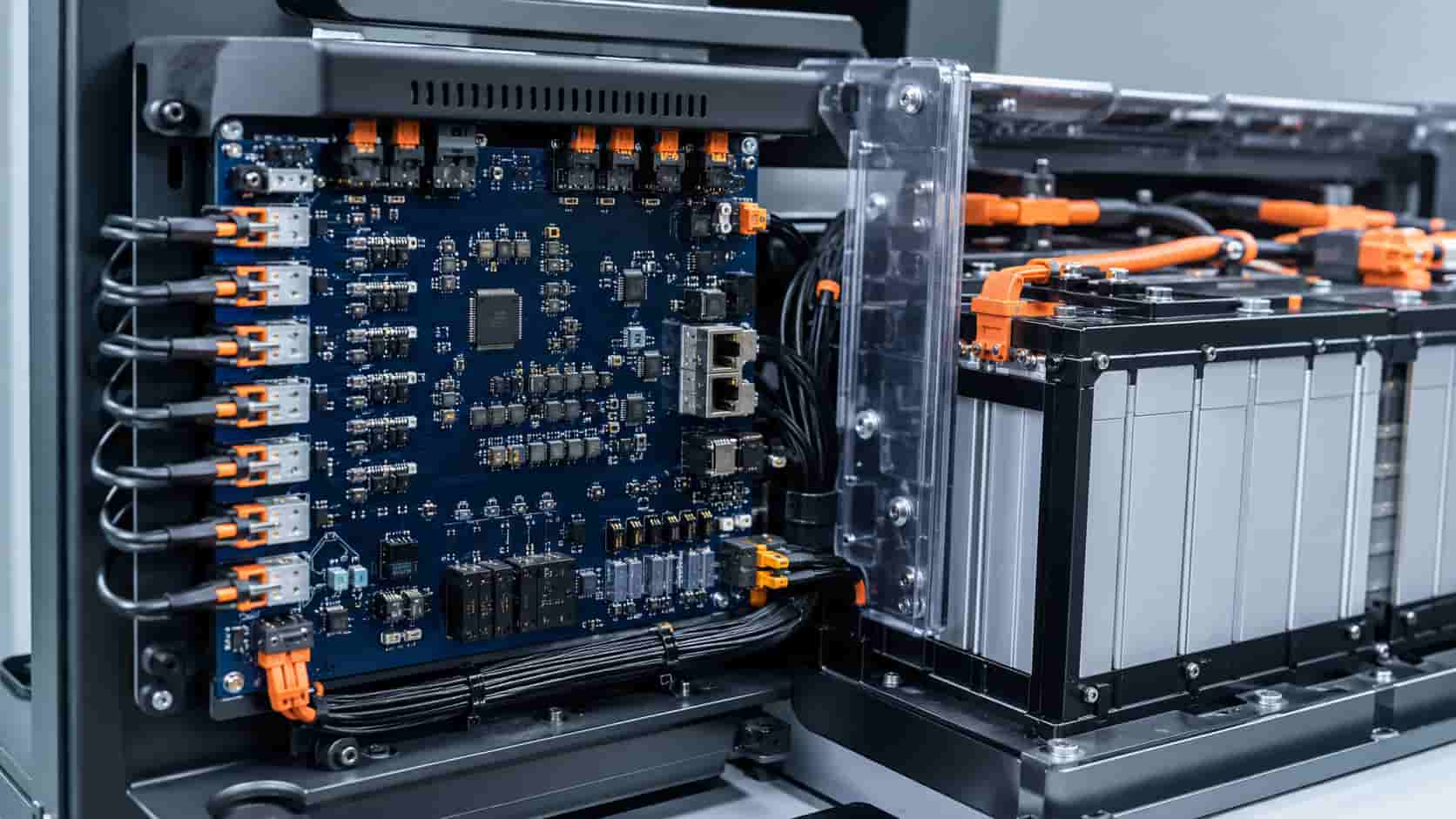
Two Different Control Layers Inside a BESS
A battery energy storage system contains several control layers. The Battery Management System, or BMS, supervises the battery and enforces its operating limits. The Energy Management System, or EMS, determines how the complete site should use the available battery capability to meet commercial or operational objectives.
The simplest distinction is protection versus optimization, but that description is incomplete. The BMS also estimates battery state and coordinates battery strings, while the EMS also manages schedules, forecasts, meters, alarms, reporting, and interfaces with other assets. Between them sit PCS controls, protection relays, plant controllers, and safety systems.
A reliable project specification must define which device owns each measurement, calculation, command, interlock, alarm, and data record. Product names vary between suppliers, so evaluate functions and authority rather than labels.
What the BMS Does
The BMS measures cell or cell-group voltage and temperature through monitoring units distributed through modules and racks. Pack or string current is normally measured through dedicated sensors. From these signals, the BMS estimates state of charge, state of health, available charge and discharge power, and fault status.
It enforces limits for overvoltage, undervoltage, overtemperature, undertemperature, overcurrent, insulation conditions where integrated, and other battery-specific hazards. Depending on architecture, it commands contactors, pre-charge circuits, cooling requests, balancing, and string isolation.
The BMS should publish dynamic charge and discharge limits rather than only a static nameplate rating. Available power can change with SOC, cell temperature, voltage spread, age, and fault condition. The PCS and EMS must respect the most restrictive valid limit.
A Typical BMS Hierarchy
Large BESS installations often use a hierarchy. Cell-monitoring units collect local voltages and temperatures. A module or rack controller aggregates data and manages local devices. A string or battery-system controller coordinates contactors, current measurement, isolation, cooling requests, and communication with the PCS or plant controller.
Terminology such as BMU, CMU, slave BMS, rack BMS, master BMS, and battery cluster controller is not standardized across all suppliers. Ask for an architecture diagram, node count, network topology, sampling rates, time synchronization, redundancy, and the effect of losing any controller or communication link.
What the EMS Does
The EMS sits above individual battery and PCS controls. It uses site load, electricity tariffs, solar forecasts, grid signals, meter readings, SOC, equipment availability, and operating constraints to determine when and how much the BESS should charge or discharge.
Typical objectives include peak shaving, energy arbitrage, solar self-consumption, backup reserve, demand response, export limiting, microgrid scheduling, or market participation. Our peak-shaving BESS sizing guide shows why an EMS needs validated interval data and tariff logic rather than a simple time schedule.
The EMS may provide dashboards, reports, alarm aggregation, user management, remote access, performance calculations, and interfaces to SCADA, a building management system, utility control center, or market platform. Some projects separate optimization software from the plant controller that executes real-time commands.
What the PCS Controller and Plant Controller Do
The PCS controller regulates the actual AC/DC conversion: current, voltage, active power, reactive power, DC-link conditions, synchronization, grid-support functions, and protection internal to the converter. It receives permitted operating limits and a power command, then determines whether the command can be executed safely. Our energy storage PCS guide explains this conversion layer in more detail.
A plant power controller or microgrid controller may coordinate multiple PCS units at the point of connection, enforce import or export limits, provide grid-code functions, manage islanding, or dispatch generators and controllable loads. On some products this controller is marketed as part of the EMS; on others it is separate.
Do not assign fast protective functions to a cloud EMS. Protection and essential real-time controls must remain available at the appropriate local layer when internet connectivity or a remote platform is unavailable.
Command Authority: Who Can Override Whom?
A safe hierarchy normally gives hard protection priority over economic dispatch. The EMS can request a charge or discharge setpoint, but the BMS can reduce the allowable power or open the battery contactors when battery limits are reached. The PCS can also reject or limit a command because of converter, AC grid, or DC conditions.
The interface should distinguish requested power, accepted power, actual power, battery charge limit, battery discharge limit, operating mode, warning, trip, and availability. A single generic fault bit is not adequate for diagnosing a multi-megawatt system.
Specify how conflicting commands are resolved among local HMI, EMS, SCADA, utility dispatch, emergency stop, fire system, and maintenance tools. Role-based permissions and mode indication help prevent two controllers from fighting each other.
BMS vs EMS at a Glance
The table below compares typical responsibilities. Actual product boundaries vary, so convert it into a project responsibility matrix and require every supplier to identify the device, data source, update rate, owner, fallback state, and test procedure for each function.
| Control layer | Primary scope | Typical inputs | Typical outputs | Authority or fallback |
|---|---|---|---|---|
| BMS | Battery monitoring, estimation, limits and protection | Cell voltage, temperature, string current, insulation and device states | SOC/SOH, alarms, contactor commands, charge/discharge power limits | Can derate or isolate the battery; must fail safely without EMS |
| PCS controller | Real-time AC/DC power conversion | DC limits, AC/DC measurements, grid state and power command | Actual power, converter status, faults and availability | Rejects or limits commands outside converter or grid conditions |
| Plant controller | Coordinates equipment at the point of connection | Site meter, PCS availability, grid commands and protection status | Unit allocation, import/export limit and grid-support commands | Maintains local control when higher-level optimization is unavailable |
| EMS | Scheduling, optimization, reporting and multi-asset coordination | Tariffs, forecasts, site load, solar, SOC, availability and market signals | Operating mode, charge/discharge schedule and plant setpoints | Must remain within BMS, PCS, protection and grid constraints |
| SCADA/HMI | Supervision, visualization, historian and operator access | Measurements, alarms, events and controller status | Authorized mode changes, acknowledgements and reports | Access must be role-controlled; display does not replace protection |
Names and boundaries vary by supplier. Convert this comparison into a project responsibility matrix that identifies the device owner, point list, update rate, command priority, timeout, fallback state and acceptance test for every function.
Data Flow Between the BMS, PCS, and EMS
The BMS normally sends SOC, SOH, cell extremes, average temperatures, string voltage and current, alarms, contactor state, and permissible charge and discharge limits upstream. The PCS sends AC and DC measurements, status, faults, availability, and delivered power. Site meters provide the point-of-connection truth used for import, export, or peak control.
The EMS sends operating modes and setpoints downward. It should not directly bypass BMS protection thresholds. All systems should use consistent sign conventions, units, timestamps, energy counters, device identifiers, and quality flags.
Common industrial interfaces can include CAN within battery equipment and Modbus TCP, IEC 61850, DNP3, OPC UA, or vendor APIs at plant level. Protocol support alone does not prove interoperability; obtain the complete point list, register map, data types, scaling, update rates, command handshake, alarm definitions, and tested firmware versions.
What Happens When Communications Fail?
Define failure behavior for every link. If the EMS-to-plant connection fails, the BESS might hold its last setpoint briefly, ramp to zero, follow a local schedule, maintain a backup reserve, or enter standby. The correct response depends on grid rules and the application.
Loss of one cell-monitoring segment may require derating or isolating the affected string. Loss of BMS limits should never cause the PCS to continue indefinitely on stale permissive data. Use heartbeat, timeout, data-quality, sequence, and plausibility checks.
Recovery also matters. Specify whether equipment restarts automatically, requires local inspection, reloads a validated configuration, or waits for operator authorization. Record the event so that intermittent network faults do not disappear after reconnection.
SOC and SOH Are Estimates, Not Direct Measurements
State of charge cannot be measured like voltage. The BMS estimates it using current integration, voltage behavior, temperature, cell models, calibration events, and other algorithms. Error can accumulate when sensors drift or the battery remains within a narrow SOC band.
State of health may represent retained capacity, internal resistance, power capability, or a supplier-specific combination. Buyers should require definitions, accuracy expectations, recalibration behavior, and validation tests. The EMS should account for uncertainty when reserving energy for backup or guaranteeing market availability.
Cybersecurity and Remote Access
BMS and EMS networks connect operational technology to vendor tools, owner systems, and sometimes cloud services. Treat remote access as a designed interface rather than a convenience feature.
Request a network architecture, asset inventory, ports and protocols, user roles, multifactor authentication where appropriate, certificate and password management, logging, time synchronization, backup and restore, vulnerability handling, software bill of materials where available, patch policy, and end-of-support dates.
Firmware and parameter updates need approval, integrity verification, rollback, version records, and a test environment. Remote access should be disabled or constrained without impairing local protective functions.
Commissioning and Acceptance Testing
Test each layer independently and together. BMS testing should cover sensor plausibility, cell and temperature limits, current measurement, contactor and pre-charge sequence, balancing logic, insulation alarms where applicable, derating, trip behavior, and loss of communication.
EMS testing should cover tariffs and schedules, forecasting inputs, meter failure, SOC reserve, setpoint limits, multi-service priorities, alarm routing, user permissions, report accuracy, network loss, restart, and daylight-saving or time-zone behavior.
Perform end-to-end scenarios that prove an EMS request is constrained by BMS and PCS limits. Verify that site-meter feedback controls the intended point of connection and that alarms remain traceable from cell or rack to the operator display.
Questions to Ask Suppliers
Which controller owns each protection, calculation, setpoint, interlock, alarm, historian tag, and report?
What exact BMS hierarchy, cell sampling coverage, sensor accuracy, balancing method, SOC/SOH algorithm, and dynamic power-limit interface are provided?
Is optimization local, cloud-based, or hybrid, and what operation continues without the cloud or internet?
Which protocols and point lists are included, and have the proposed BMS, PCS, EMS, meters, and firmware versions been integration-tested together?
Who can change protection thresholds, dispatch rules, firmware, and tariff settings, and how are changes approved and audited?
What are the fail-safe and recovery states for every communication link and controller failure?
Who owns ongoing software licenses, cloud fees, cybersecurity updates, data export, technical support, and end-of-life migration?
Where Kexingyu Power Fits In
Kexingyu Power can discuss integrated BESS architectures involving batteries, BMS, PCS, EMS, switchgear, meters, and site-level controls. Exact functionality, protocol support, redundancy, hosting, and cybersecurity scope must be confirmed for the proposed project configuration.
Provide the control narrative, single-line diagram, application priorities, point-of-connection requirements, communications standards, owner SCADA interface, remote-access policy, alarm philosophy, and acceptance scenarios. This turns “BMS and EMS included” into a testable control-system scope.
Final Takeaway
The BMS protects and characterizes the battery. The EMS decides how the site should use the capability that remains available. The PCS executes power conversion, while protection and plant controls enforce electrical and grid constraints.
A successful BESS needs all layers to exchange trustworthy data, respect a defined authority hierarchy, fail safely, and remain supportable throughout the project life. Procurement should therefore specify interfaces and test cases—not only controller brand names.
Frequently Asked Questions
Practical questions about BMS and EMS integration.
No. The EMS optimizes site operation, while the BMS monitors and protects the battery and publishes safe operating limits. Economic dispatch must never bypass battery protection.
The BMS must continue essential battery monitoring and protection without the EMS. The BESS may lose optimization or scheduled operation, but it should move to a defined safe local mode.
The EMS or plant controller usually requests a power setpoint. The PCS controller executes conversion only within its own limits and the dynamic charge and discharge limits supplied by the BMS.
Typical data includes SOC, SOH, voltage, current, temperature extremes, cell spread, contactor state, alarms, availability and permissible charge and discharge power. The exact point list and update rate must be specified.
CAN is common inside battery equipment, while Modbus TCP, IEC 61850, DNP3, OPC UA or APIs may be used at plant level. Protocol names alone are insufficient; verify the point map, scaling, timing, handshake and firmware versions.
Use heartbeat and timeout logic. The system should derate, ramp to zero, isolate or enter another approved local mode according to the control narrative. It must not continue indefinitely using stale battery limits.
Test sensor and alarm behavior, dynamic battery limits, contactors, PCS command limiting, EMS dispatch, meter feedback, communications loss, restart, user permissions, time synchronization, alarm traceability and end-to-end fault scenarios.
Recent Posts
Switchgear Lead Times in 2026: A Buyer’s Planning Guide
Switchgear Lead Times in 2026: A Buyer’s Planning Guide Realistic timelines vary significantly by voltage class and type — here’s how to plan procurement without
What Is BESS? A Guide to Battery Energy Storage Systems for C&I Buyers
What Is BESS? A Guide to Battery Energy Storage Systems for C&I Buyers A clear explainer on what BESS systems actually are, how the pieces
Switchgear vs Transformer Lead Times: What EPC Contractors Need to Know
Switchgear vs Transformer Lead Times: What EPC Contractors Need to Know A practical breakdown of why these two equipment categories behave differently in procurement, and