
Battery and Power Cable for Mobile Robots: High Current in Tight Spaces
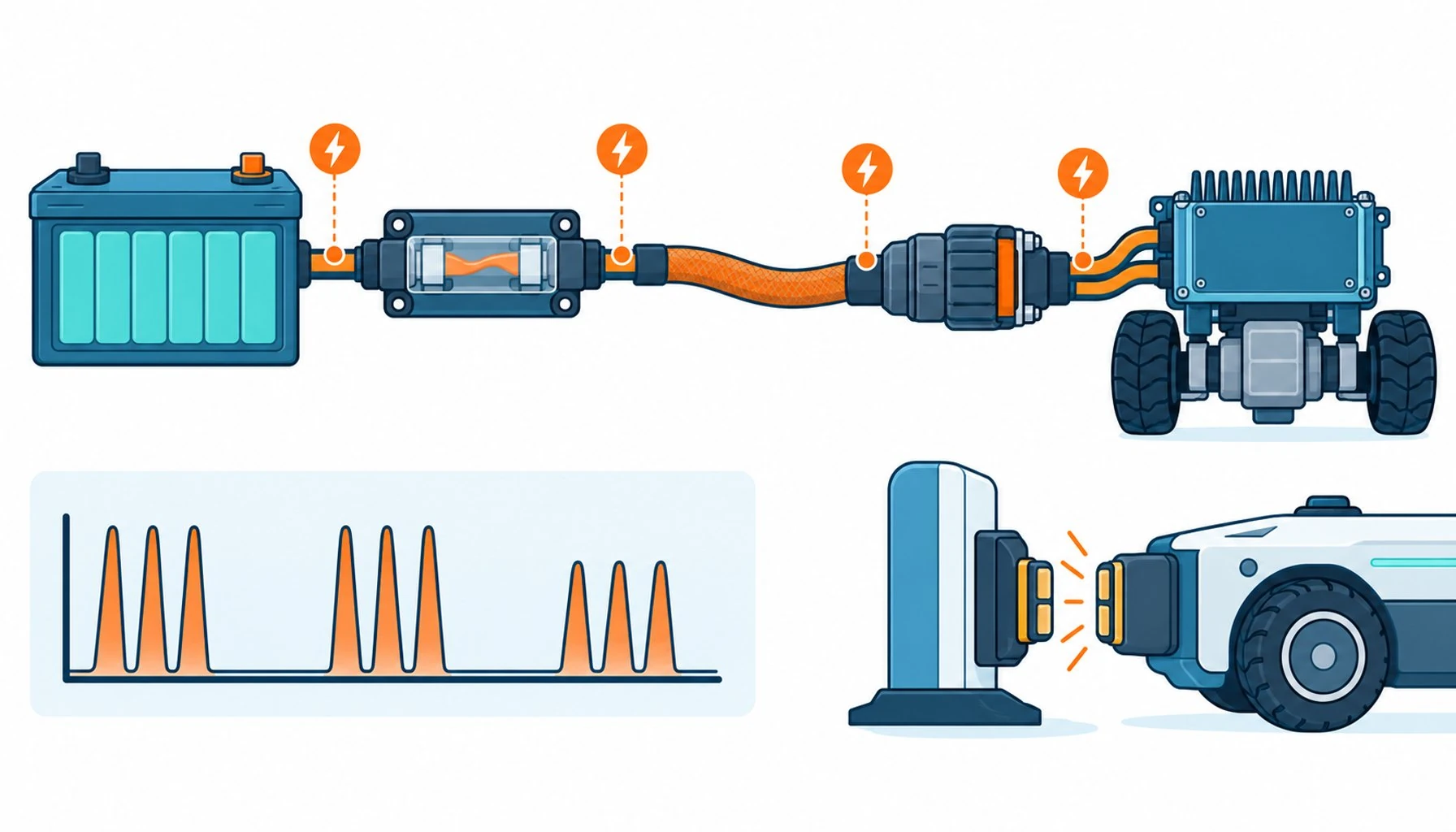
Quick Answer: Mobile robot battery cable must carry peak currents in millivolt-drop budgets, flex through tight chassis routing, and survive charge cycles and vibration; the specification starts with the shift-long voltage drop, not the ampacity table.
The battery cable on a mobile robot is the artery of the whole machine, and it is specified under constraints no stationary installation ever faces. The current is high, often the largest on the vehicle, and it flows through a chassis that is short, tight and full of things the cable must not touch. The machine vibrates, twists on suspension, and recharges on cycles that thermal-cycle the harness every shift. And the budget is unforgiving: every millivolt lost in the cable is capacity the fleet never uses, which turns cable sizing into a range question, not just a safety question. This guide walks the battery and power cable decision for AGVs, AMRs and mobile platforms: the electrical sizing, the mechanical routing, the charging interface, and the specification language that ties them together.
Introduction
Fleet operators feel battery cable problems in a language of symptoms: a vehicle that sags on acceleration where its siblings do not, a contactor or connector running hot, range that drifted down over months, a charge session that ends early. Underneath most of these sits resistive loss, in a conductor sized from a table, in a crimp that was never measured, in a connector that was chosen for availability rather than current. The engineering response is to treat the power path, battery, protection, cable, connector, drive, as one circuit with one budget, and the cable is the longest, most flexible part of that path.
The battery chemistry underneath sets the voltage window, and the trade-offs between lithium chemistries that shape that window are compared in the guide to LiFePO4 and other battery types; this article picks up where the chemistry ends, at the terminals.
Sizing: The Voltage Drop Budget Decides, Not the Ampacity Table
Ampacity tables answer the safety question, what conductor will not overheat at a given current, and for the short runs inside a mobile platform they almost never bind. The binding constraint is voltage drop: at 24, 48 or 80 volts, a one-volt loss is a real percentage of the machine’s operating window, lost to heat in copper instead of delivered to the drive. Sizing therefore starts from the budget, total permitted drop from battery to drive at peak current, and works backward to conductor cross-section over the actual route length, including both the positive and the return path. Peak versus continuous current matters too: acceleration peaks last seconds, but the cable’s thermal mass is small in a tight chassis, and the duty cycle of the application, sprints and idle, belongs in the sizing calculation.
The sizing method itself, drop calculations and the tables behind them, follows the standard approach in the cable sizing guide, applied here with the mobile-platform twist that the route length includes every loop, service bend and service loop the harness actually takes.
Routing: High Current in a Tight, Moving Chassis
The mechanical problem is strict: large cross-section conductors do not like tight bends, and mobile platforms are made of tight bends. The routing rules that matter: respect the minimum bend radius of the chosen construction everywhere, not on average, with the suspension travel and door swings included in the geometry; clip the cable so vibration does not work any termination; keep the run away from heat sources and sharp sheet-metal edges; and leave service loops where maintenance will disconnect anything, because a battery cable re-terminated under tension is a future fault. Flex-rated constructions matter even for cables that barely move, because vehicle duty is vibration duty, and the fine-stranding logic that serves bending also serves fatigue under shaking, and the vibration failures it prevents sit within the broader catalogue of why cables fail.
The Charging Interface: A Wear System With Its Own Cable Rules
Charging stresses the power path differently: high current in short sessions, connectors that mate thousands of times, cables that coil and uncoil at docks, and thermal cycling every session. The charging cable wants flex-rated construction sized by the same drop budget at charging current, strain relief that keeps the flex away from the connector contacts, and jacket compounds matched to the dock environment, whether that is a warehouse floor or an outdoor yard. The contact and connector side of charging wear, and the maintenance approach that keeps the interface honest, deserves its own maintenance treatment, and the same physics applies to the battery-side segment of the harness.
Protection, Measurement and the Rest of the Path
The cable lives inside a protective architecture: fusible protection or breakers sized for the battery’s fault capability, contactors rated for the inrush reality of drive electronics, and insulation monitoring where the safety case demands it. Battery system safety has its own discipline, and the thermal behavior that makes lithium systems demand respect is covered in the guide to lithium battery thermal runaway, with the cable’s role being to stay a conductor and never become a heat source or a short-circuit path. The maintenance symptoms operators learn to read early, drift, heat and early session endings, parallel the classic failure list in the guide to stationary battery problems. The monitoring side of the system, what the BMS watches and what the fleet system watches, follows the architecture questions discussed in the guide to BMS versus EMS, scaled down to vehicle size.
The table below condenses the sizing and specification decisions into the cases a mobile-platform engineer actually meets.
When a fleet problem does appear, the symptom points at a segment of the power path, and the diagnostic table below maps the common ones to their likely owners before anyone starts replacing cable.
| Decision | What drives it | Specification answer | Common mistake |
|---|---|---|---|
| Conductor cross-section | Voltage drop budget at peak and continuous current, route length both ways | Sized from the budget, ampacity verified as a floor | Sizing from the ampacity table and losing percent of range in copper |
| Conductor class | Vibration duty, tight radii, service loops | Fine strand, flex-rated construction | Coarse battery cable from the automotive shelf, fatiguing at terminations |
| Jacket compound | Floor environment, oil, abrasion at clips | PUR default, temperature window matched to charging heat | PVC in a wet, abrading chassis |
| Connector and crimp | Peak current, thousands of cycles, thermal load | Current-rated connector with measured crimps, strain relief separated | Availability-chosen connectors whose contacts become the drop |
| Charging segment | Coiling at the dock, session thermal cycling | Flex-rated, drop-budgeted at charging current, dock-matched jacket | Reusing drive-side cable for the charge path |
| Protection placement | Battery fault current, harness length to protection | Protection sized and placed per the fault study | Long unfused runs from the battery terminal |
| Symptom | Likely owner | Confirming measurement | Typical fix |
|---|---|---|---|
| One vehicle sags on acceleration, siblings fine | Termination or connector resistance in its power path | Drop measurement segment by segment under load | Re-crimp or replace the degraded joint |
| Connector housing hot after a shift | Connector contacts or crimp | Thermal check under load; drop across the mated pair | Current-rated connector replacement, crimp verified |
| Fleet-wide range drift over months | Battery aging, not the harness | Compare drop at same current across vehicles | Pack service or replacement planning |
| Charge sessions end early on dock units | Charging interface wear | Contact resistance trend at the dock | Contact maintenance schedule; cable strain relief check |
| Intermittent undervoltage faults at peak draw | Undersized conductor or protection placement | Drop at peak versus the original budget | Re-size to the budget; recheck the protection study |
When Battery Cable Rules Are Not the Whole Answer
Honest limits: the cable is one part of the power path, and several range and heating symptoms trace elsewhere. Connector contact resistance degrades quietly and belongs to the maintenance plan, not the cable specification. Battery internal resistance grows with age and chemistry, and a fleet losing range together may be an aging pack question, not a harness one. Thermal management of the battery compartment drives charging behavior in ways the cable cannot influence. And the control layer, how the vehicle manages current draws and charging sessions, belongs to the power electronics and software scope. The cable specification here is necessary, checkable and often decisive, and it works inside a system whose other parts carry their own disciplines.
RFQ Checklist: Specifying Mobile Robot Power Cable
Bring the power path to the supplier in numbers:
- Electrical window: system voltage, continuous and peak current, permitted total drop at peak
- Route geometry: actual harness length with loops, tightest radius, suspension and door motion
- Environment: floor fluids, abrasion points, temperature including charging heat
- Charging segment: current, coiling duty, dock connector interface
- Evidence required: flex and vibration-rated construction data, crimp and connector system specification
- Protection plan: where protection sits, and the fault current it must interrupt
Conclusion
Battery cable on a mobile robot is sized by a voltage drop budget that the fleet feels as range, routed through a chassis that punishes stiffness, and exercised by charging cycles that thermal-cycle the harness every shift. The specification follows from those facts: fine-stranded flex-rated construction, drop-budgeted cross-sections, jackets matched to the floor, connectors and crimps treated as current-carrying components, and the charging segment engineered as the wear system it is. Fleets that specify this way keep their voltage at the drive; fleets that size from tables pay for it in range and downtime.
Kexingyu Cable Group (KXYE) builds fine-stranded, high-current flexible cable for mobile platforms, with crimp and connector system support and test data that follows the vehicle’s duty. Send your platform’s power path through the RFQ page, and we will size the artery to the shift it must run.


