
EN 60204-1 Explained: Electrical Wiring Rules for Machinery
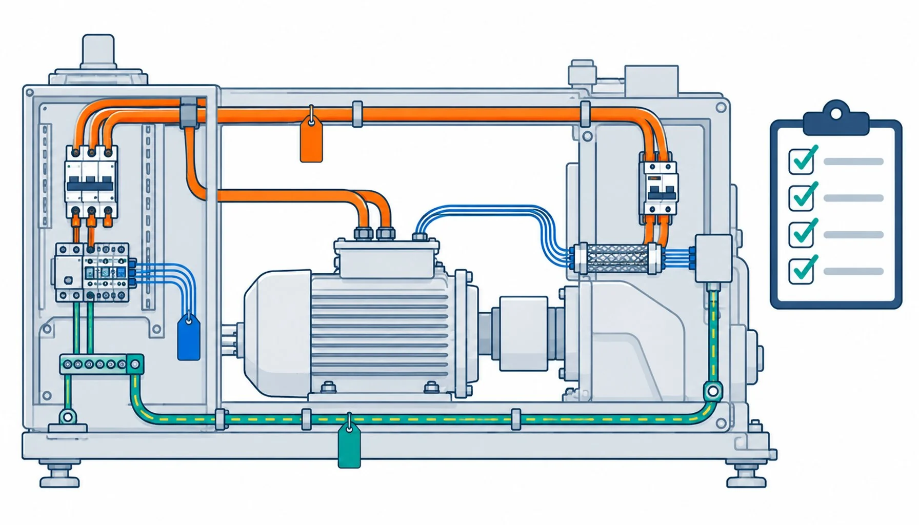
Quick Answer: EN 60204-1 is the wiring constitution of industrial machines: it sets what conductors, identification, protection, bonding and shields inside a machine must achieve, and machine builders who read it as a checklist pass inspections that others argue about.
Every machine shipped into the European market, and many shipped beyond it, carries the fingerprints of EN 60204-1 whether its builder knows the number or not. The standard governs the electrical equipment of machines: how conductors are sized and identified, how protection is arranged, how the cabinet and the machine frame are bonded, how shields and signal circuits are handled, and how the whole electrical system proves itself at verification. For cable buyers and machine builders it is the frame around every harness decision, and this guide translates its requirements into the practical decisions each one drives.
Introduction
The standard sits in a family: the machinery directive defines what a machine must achieve to move in its market, and EN 60204-1 is the document that harmonizes the electrical equipment layer of that achievement. Reading it as an inspector reads it, requirement by requirement, is the habit that separates machines that pass from machines that document their way into arguments. This guide walks the standard’s themes in the order a builder meets them: the conductor rules, protection and disconnect, bonding, signal wiring and shields, identification, and verification, with the cable and cabinet decisions each theme carries.
The wider context of the machine’s electrical environment, from the supply characteristics to the drives inside it, connects this standard to the equipment-level frameworks summarized in the motion cable standards map, and this guide is the deep dive on the wiring layer of that map.
Conductors: Sizing, Types and What the Standard Demands
The conductor rules are practical: conductors must be sized for the current they carry with the insulation rated for the voltage class, protected against the mechanical and thermal environment of the machine, and installed so their protection, routing and terminations remain sound through the machine’s life. Copper is the default assumption, aluminum conductors carry additional requirements, and reduced-conductor control circuits follow their own sizing logic. The standard does not brand cables, but its requirements filter catalogs effectively: a cable that cannot meet the mechanical protection, temperature and identification demands of the machine’s environment is not compliant wiring regardless of its datasheet virtues. The conductor-side basics, sizing and protection logic, follow the same engineering as the general cable sizing method, applied inside the machine’s frame.
Protection and Disconnect: The Architecture Around the Cable
The standard’s protection requirements shape the electrical architecture the cables serve: overcurrent protection arranged so faults are cleared selectively, disconnecting means that make the machine safe to service, and the prevention of unexpected start-up. For the harness, three consequences matter. Protection placement defines how far unfused conductors run, which is a routing decision as much as an electrical one. The disconnecting arrangement defines which cable ends carry stored-energy and lockout obligations during service. And the verification regime defines what every circuit must prove before the machine ships, which is why the harness documentation, continuity, insulation resistance, bond integrity, belongs to the build process rather than the paperwork at the end.
Bonding: The Requirement That Outlives Every Failure Argument
The bonding and earth-continuity requirements are among the standard’s most consequential, and the most commonly under-executed: protective bonding conductors must connect every exposed conductive part into a continuity chain that survives vibration, corrosion and service interventions, with terminations identified and the continuity proven by measurement. For harness builders the practical rule is that bonding is a designed path, not an incidental contact: dedicated protective conductors, identified, sized for the fault duty, routed to survive the machine’s motion and maintenance, and verified. The cabinet-side execution of this architecture, bars, terminals and the layout that keeps it maintainable, is treated in the guide to control cabinet construction.
Signal Wiring, Shields and the EMC Frame
The standard requires that signal circuits be arranged so that interference does not impair the machine’s functions, and its guidance on separation, shielding and the routing of sensitive conductors is the compliance frame around the EMC practices that moving machines need. For the harness this means separation between power and signal runs, shields landed in a manner that supports the machine’s EMC plan, and the identification that keeps the arrangement maintainable across the machine’s life. The detailed shield architecture that drives and motion duty demand goes beyond the standard’s floor, into the territory covered by the moving-machine EMC grounding guide, but the standard’s requirement is the legal frame the detail serves.
Identification and Documentation: The Underrated Half
Half the standard’s practical value is identification and documentation: conductors identified consistently, terminals marked to match the drawings, and the electrical documentation, diagrams, ratings, verification records, delivered with the machine. For harness work the identification rules decide marking schemes, color conventions and the printed-meter and label schemes that make service possible years later. Machines built with the identification discipline pass their verification once and stay serviceable; machines built without it pay for the omission at every intervention, and the standard’s requirements here are cheap insurance compared to the alternative.
The requirements across themes compress into the table below, ordered as a build meets them.
| Theme | Core requirement | Cable decision it drives | Cabinet decision it drives |
|---|---|---|---|
| Conductors | Sized, protected, mechanically sound for the machine environment | Cable rated for the machine's voltage, temperature and mechanical duty | Routing and ducting that protects the run |
| Protection and disconnect | Selective overcurrent protection, safe servicing | Unfused run lengths minimized; ends marked for lockout | Protective device placement and ratings |
| Bonding | Proven protective continuity to every exposed part | Dedicated, identified protective conductors sized for fault duty | Bonding bars and terminal architecture |
| Signal wiring and shields | Functions unimpaired by interference | Separation and shield practice supporting the EMC plan | Entry filtering and separation discipline |
| Identification and documents | Consistent marking, delivered documentation | Marking schemes, labels, printed lengths | Terminal marking matched to drawings |
| Verification | Continuity, insulation and function proven before delivery | Harness test records per circuit | Verification test plan and records |
Verification: Proving the Machine Once, Properly
The standard closes with the verification regime: continuity of protective bonding measured, insulation resistance tested, and the functions of the electrical system checked before the machine enters service. For builders this is the moment the wiring discipline pays or exposes itself, and the practice that makes verification routine is building it into the harness process: per-circuit test records, bond measurements at defined points, and documentation generated as the machine is built rather than reconstructed afterward. The verification battery itself is short, and the table below is the version that belongs in a build plan.
| Test | Method | Pass condition | Failure response |
|---|---|---|---|
| Protective bonding continuity | Measure from each exposed part to the earth point | Low resistance per the standard's requirement, all points | Find and correct the bonding path before anything else |
| Insulation resistance | Test circuit groups against each other and earth | Above the standard's threshold at the test voltage | Locate the wet, damaged or compromised section; dry or replace |
| Voltage test where required | Dielectric test per circuit class | Withstands without breakdown | Quarantine and rework the failed circuit |
| Function checks | Operate each function, including emergency stop | All functions correct, safety functions proven | Correct wiring or configuration; re-verify |
| Records | File per-circuit results with the machine documentation | Complete, traceable, signed | Rebuild the record now; retrofit records cost more later |
When the Standard Is Not the Whole Picture
Honest limits: EN 60204-1 is the electrical equipment layer of machine compliance, not the whole machine directive, and it does not replace the machine-level risk assessment, the specific product directives that certain machines carry, or the performance engineering that makes a harness survive its duty. Machines with special environments, explosive atmospheres, food machinery, medical and semiconductor equipment, carry additional and sometimes overriding requirements, and machines crossing markets carry the certification layers planned per the equipment certification checklist. And the standard’s floors, like all floors, can be met while the machine still fails in service: a compliant harness with inadequate flex construction for its moving axes is legal and short-lived. The standard frames the electrical obligations; the duty specification, the subject of most of this series, still decides whether the machine keeps running.
RFQ Checklist: Building to the Standard
Attach the standard to the build itself:
- Scope statement: which machine family, which market, which edition of the standard applies
- Conductor plan: types, sizing and identification per circuit, documented against the standard’s clauses
- Bonding design: the continuity chain, conductor sizing and verification points
- Signal plan: separation, shielding and landing architecture supporting the EMC design
- Documentation package: diagrams, ratings and records delivered with the machine
- Verification plan: what is measured, where, with which instruments, before shipment
Conclusion
EN 60204-1 is the wiring constitution of industrial machines, and its requirements translate directly into harness and cabinet decisions: conductors sized and protected for the machine’s environment, bonding designed as a verified path, signal wiring arranged against interference, identification that makes the machine serviceable, and verification that proves it all once, properly. Builders who treat the standard as a design input build machines that pass and stay serviceable; builders who treat it as paperwork rediscover its requirements at every inspection and every fault.
Kexingyu Cable Group (KXYE) supplies machine cable and harness support aligned to machinery wiring requirements, with documentation packages that feed verification directly. Send your machine’s electrical scope through the RFQ page, and we will quote to the standard, not around it.


