Underground Mobile Substations: Cable for High-Voltage Rubber Feeders
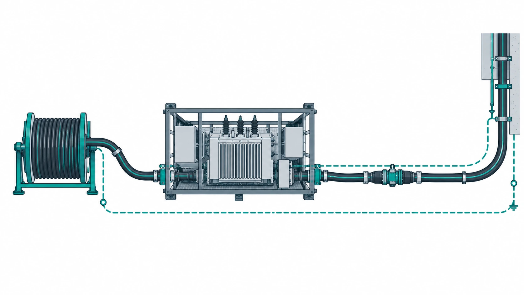
Quick Answer: A mobile substation moves the feed point closer to the face, and everything between it and the load has to be trailed, coupled and monitored rather than fixed. That makes the cable selection a system decision: the HV rubber feeder, the couplers that join it, the earth continuity monitoring that watches it, and the protection settings that trip it. This guide covers what to specify, what evidence to demand, and what to freeze before the RFQ goes out.
Introduction
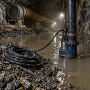
Underground distribution has one structural problem: the load moves. A face advances, a heading extends, and the substation that fed it yesterday is now too far away to hold voltage at the machine. Moving the substation closer is the standard answer, and it converts what was a fixed feeder into a mobile high-voltage connection.
That conversion changes the cable specification more than buyers expect. A fixed HV feeder is buried or tray-mounted and left alone for years. A mobile substation feeder is reeled, coupled, uncoupled and moved, and it carries a voltage high enough that the earth continuity monitoring and the couplers are as much part of the specification as the conductor. The equipment itself, the transformer and the switchgear on the skid, belongs to our note on the mining power equipment package and to the prefabricated substation for mining; this guide covers the cable side.
What a Mobile Substation Changes About Cable
Three things change at once when the substation starts to move.
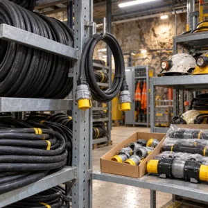
The feeder is handled. Cable is wound on a reel or coiled on a skid, dragged into position and connected by hand. The mechanical duty that a fixed feeder never sees, repeated bending and handling, becomes the governing load.
The connection is broken and remade. Couplers are the weak point of a mobile HV system, and their ingress protection and sealing are what decide whether moisture reaches the screen after the tenth move.
Earth continuity has to be watched. On a fixed feeder, earth continuity is an installation check. On a mobile feeder, the screen or pilot core is monitored continuously, because a broken earth path on an HV cable is a safety condition rather than an inconvenience. The monitoring arrangement is part of the cable specification, not an afterthought in the relay panel.
The practical consequence is a specification with two halves: the cable construction, and the interface hardware that goes with it.
The High-Voltage Rubber Feeder
Where the feeder has to be handled, the answer is usually a rubber-sheathed HV construction rather than a fixed XLPE cable, and the difference is in the layers rather than the voltage class.
Conductor and screen. A flexible conductor survives repeated handling, and a semi-conductive screen over the insulation controls the electric stress at the conductor and at the screen edge. In a mobile construction, the screen has to tolerate bending without separating from the insulation, which is a manufacturing question rather than a material one.
Sheath and reinforcement. The sheath takes the abrasion of being dragged and the load of being coiled. Where the cable is dragged over rock, a reinforced sheath or an armour layer is part of the specification rather than an option, and the trade-off between the two is set out in our note on armoured versus unarmoured cable.
Bend radius. The tightest radius is usually at the reel or the substation entry, not along the route. A mobile HV cable’s rated radius is a handling figure rather than a routing figure, and it has to be stated at the point where it is worst.
For the fixed section between the main substation and the mobile one, a conventional armoured XLPE cable is often the right answer, and the medium-voltage armoured constructions in our range are described in the MV armoured cable range.
Couplers, Terminations and Earth Continuity
The connectors on a mobile HV feeder deserve their own specification line, because they fail before the cable does.
Couplers. Rated voltage and current, ingress protection for the assembled state, and compatibility with the cable’s construction and diameter. A coupler that is sealed when new and unsealed after repeated handling is the most common cause of a moisture fault on a mobile feeder. Ask for the type test evidence for the assembled state, not for the component.
Terminations. Where the feeder ends in a substation or a junction box, the termination has to be rated for the same stress as the cable. Our note on MV cable termination testing covers what to witness at that interface.
Earth continuity monitoring. The screen or pilot core is monitored for continuity as part of the machine’s protection scheme. The specification should state the monitoring method, the continuity limits and how the screen is arranged, because the cable’s screen construction is what makes the scheme work.
The table below maps the parts of a mobile substation cable system against what to specify, what to demand as evidence, and how each one fails.
| Part | Duty on Site | What to Specify | Evidence to Demand | Cost and Lead-Time Driver | How It Fails |
|---|---|---|---|---|---|
| HV rubber feeder | Handled, reeled and dragged between positions | Flexible conductor, screened insulation, reinforced sheath or armour, stated bend radius at the reel | Flex data at the declared radius, screen integrity after bending, sheath abrasion results | Screened mobile construction costs more than a fixed feeder | Screen damaged by handling, moisture into the insulation, an earth fault |
| Couplers | Connected and disconnected on every move | Rated voltage and current, ingress protection for the assembled state, compatibility with the cable | Type test evidence for the assembled coupler, sealing verification | Cheap against the labour of a joint; incompatible kits are the expensive version | Moisture into the screen after repeated handling, a fault that returns to the same coupler |
| Terminations and junctions | Fixed at the substation and at any intermediate box | Rated stress, termination type, and the space available in the enclosure | Termination test evidence, dimensions checked against the box | Termination quality is set by the installer as much as by the kit | Partial discharge, tracking, a fault that develops rather than appears |
| Earth continuity monitoring | Continuous, as part of the machine protection scheme | Screen or pilot core arrangement, monitoring method, continuity and earth loop limits | Screen continuity on the finished length, monitoring scheme drawing | The cable's screen construction is what makes the scheme work | A safety function that reports healthy until the moment it is needed |
| Fixed feeder to the substation | Fixed, buried or tray-mounted, rarely touched | Voltage class, insulation level, armour, fault level and protection coordination | Type test and routine test records, fault level calculation | Copper and armour drive the price; length drives the drum planning | Corroded armour stops being an earth path, voltage drop at the far end |
Sizing the Mobile Feeder
A mobile substation exists to shorten the electrical distance, so the sizing inputs are about what remains.
Position and route. State how far the substation will sit from the load and how that distance changes as the face advances. The feeder has to work at the longest position, not the average one.
Load and starting duty. Give the continuous and starting current at the far end, plus the starting frequency. A face machine starting loaded several times a shift imposes a duty a steady-state rating does not describe.
Voltage drop and fault level. High-voltage feeders drop less voltage per metre than low-voltage ones, but the load is concentrated and the machine still has a voltage window. Fault level at the substation is the other input, because it sets the protection settings the cable has to coordinate with.
Earth loop impedance. Protection is set against the circuit’s earth loop impedance, which on a mobile feeder includes the couplers as well as the cable. That makes the monitoring scheme and the earth loop calculation part of the same specification task.
Where the moving substation removes a long low-voltage run entirely, the transformer capacity is part of the same decision, which our note on transformer capacity sizing covers from the equipment side.
Approval and Test Evidence
Underground HV cable is specified against a national standard, and the equivalent code from another market is a starting point rather than a substitution. Our note on MV cable standards across IEC, GB and BS explains how the same cable is described differently in each system.
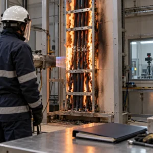
What to demand with the quotation is more specific than a standard number. Ask for the construction drawing with conductor class, insulation, screen arrangement and sheath; the type test and routine test records for the exact construction quoted; the coupler’s type test for the assembled state; and, where the destination is underground and regulated, the mark issued against that construction. A certificate names a construction rather than a brand, so substituting a compound breaks it on paper even when the cable looks identical.
What to Freeze Before the Order Goes Out
These five items are cheap at specification stage and expensive once the skid is on site.
| Decision | What to State | Evidence to Attach | Cost of Leaving It Open |
|---|---|---|---|
| Longest position | The furthest the substation will sit from the load, and the distance it travels | A layout showing the cable route at its longest position | A feeder that is short at the end of the block |
| Coupler standard | Coupler type, rating and compatibility with the cable construction and diameter | Type test evidence for the assembled coupler | A correct cable that will not couple to the substation |
| Earth continuity scheme | The monitoring method, continuity limits and how the screen is arranged | A monitoring scheme drawing and screen continuity records | A safety function that reports healthy until it is needed |
| Fault level and settings | Prospective fault current and the protection settings the cable must coordinate with | The fault level calculation and a single line diagram | A feeder that defeats the earth fault protection |
| Handling and storage | Reel or skid, bend radius at handling, storage conditions and inspection interval | A handling and storage instruction written into the order | Damage before first energisation, on a cable nobody has energised yet |
Cost Structure and Lead Time
A mobile HV feeder is priced from the copper outward, and the screened mobile construction costs more than a fixed feeder of the same rating. The screen, the semi-conductive layers and the reinforced sheath are all manufacturing steps that a fixed cable does not need, and a quotation that is unexpectedly cheap is usually a quotation for a fixed construction.
The couplers are a separate line and should be compared as a system. A cheaper coupler that seals badly after repeated handling is the most expensive item in the order, because it takes the cable out of service for a fault that lives in the joint.
Lead time follows the mining pattern. Stock constructions ship in days; a made-to-order screened mobile feeder runs on the sheath and screening lines; a certified underground construction is the longest, because the approved compound and the standard’s test regime sit on the critical path. Plan back from the shutdown, not forward from the specification date.
Incoming Inspection and Commissioning Checks
Against the drum or skid, before anything is cut. Count and verify the marked lengths and photograph the markings, including the construction code, and check the couplers against the packing list.
Electrical checks. Conductor resistance and continuity, insulation resistance, and screen continuity end to end at the declared limit. On an HV mobile feeder the screen is a safety path, so it is checked before energisation rather than after.
Coupler and termination checks. Verify the sealing for the assembled state, the torque values and the ingress protection, and record them against the coupler’s identity so a repeat fault can be traced to the hardware rather than to the cable.
When a Mobile Substation Cable Specification Is Not the Answer
When the real fault is protection coordination. A mobile feeder tripping on earth fault well above its setting is telling you about the earth loop, not the cable. Replacing the drum without doing the calculation repeats the fault at the next position.
When the coupler is the weak point. If faults cluster at one coupler rather than spreading along the feeder, the answer is the interface, not a heavier cable. Coupler failures repeat when the handling routine and the sealing are not changed with the hardware.
When the substation has outgrown its cable scheme. A skid that gains a second outgoing feeder needs its earth continuity and protection scheme revisited, not just a second cable. Adding to a mobile substation without revisiting the scheme is how a safe arrangement becomes an unmonitored one.
When a fixed construction is quoted for a mobile duty. The cheapest way to fail this order is to accept a fixed HV cable for a feeder that will be reeled. The first move will damage the screen, and the fault will be attributed to the installation rather than to the specification.
When price is the only variable asked about. A mobile HV feeder bought on unit price alone is judged in service, and the cost of an earth fault underground is measured in a stopped face rather than in money.
RFQ Checklist
- Longest distance between the substation and the load, and how it changes
- Whether the feeder is reeled, coiled or laid for each position
- Voltage class, insulation level and prospective fault current
- Continuous and starting current at the far end, plus starting frequency
- Earth loop impedance and the protection settings the cable must coordinate with
- Screen or pilot core arrangement, plus the earth continuity monitoring method
- Coupler type, rating, ingress protection and compatibility with the construction
- Minimum bend radius at the reel and at the substation entry
- Sheath grade and reinforcement, for handling and for the roadway environment
- Termination type and the space available in the enclosure
- Standard and mark the destination mine accepts, for the exact construction
- Handling, storage and inspection instructions, plus the copper basis validity window
Conclusion
A mobile substation is bought as a system, and the cable, the couplers and the earth continuity scheme have to be specified together. State the longest position, the fault level, the monitoring method and the coupler standard, and the feeder stops being a length of cable and becomes a distribution arrangement that moves with the face.
Kexingyu Cable Group (KXYE) has supplied electrical cable from Quanzhou since 1996, including the screened, rubber-sheathed and armoured constructions that underground distribution calls for, along with the couplers, terminations and accessories that go with them. Send us the substation layout with the feeder route, the fault level, the monitoring arrangement and the site conditions, and we will come back with the constructions, the test evidence that applies to each, and a delivery plan against your shutdown window. The fastest route is a request for quotation.