
MV Cable Termination and Testing in Data Center Substations: What to Buy and What to Witness
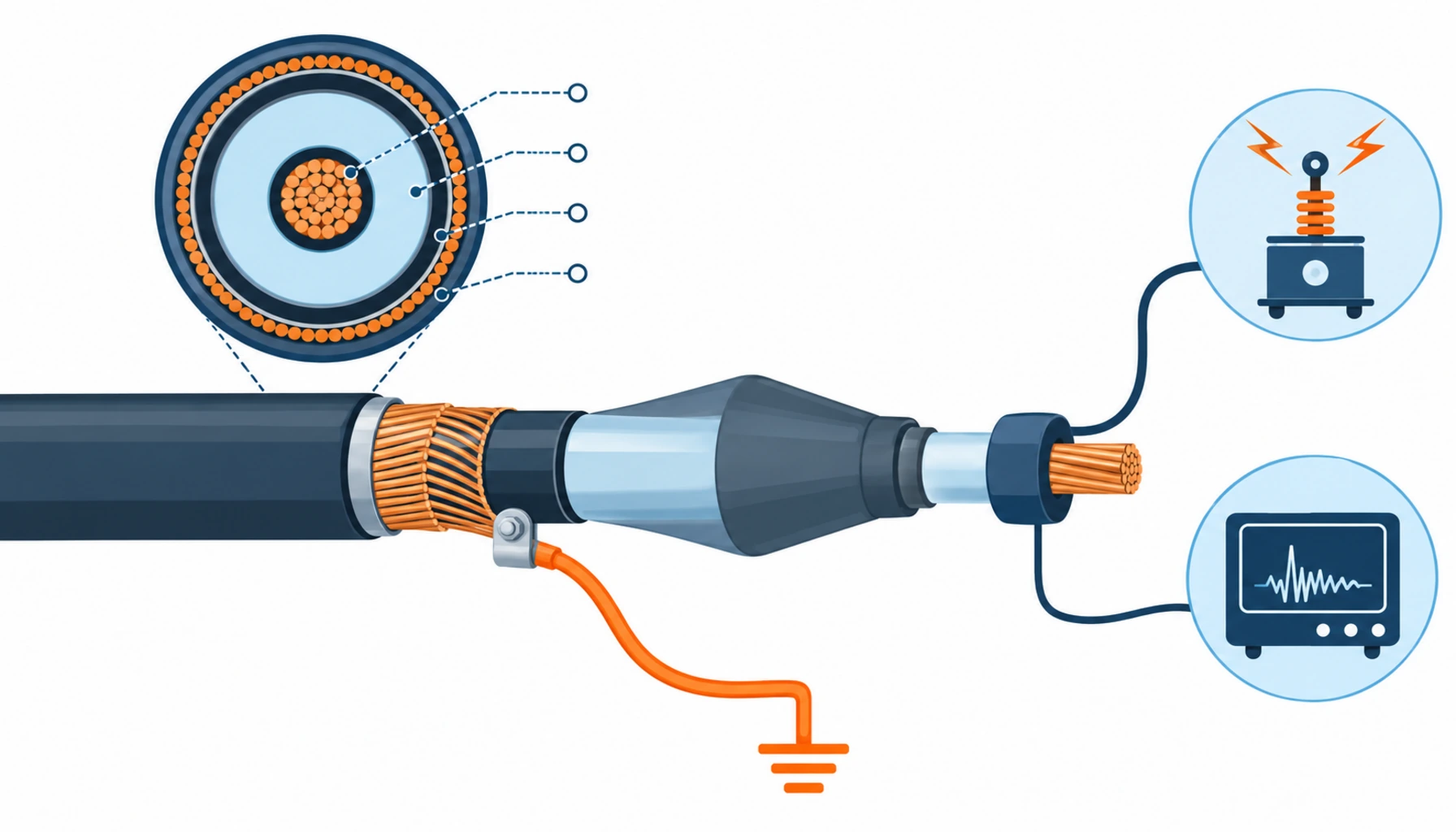
Quick Answer: A medium voltage termination is a small part of a substation package by cost and the most likely part to fail in service. The reason is that the termination is not really a component purchase, it is a competence purchase: the warranty depends on the kit, the installer and the installer’s certification being the same three things the kit manufacturer approved. What belongs in the enquiry is the kit type, the named installer and certification, the workshop or site conditions, and a named withstand test method. What belongs in your witness scope is the screen earthing arrangement and the pass criteria, because those are the two things that cannot be corrected once the cable has been cut back.
MV terminations occupy an awkward position on a data center project. The cable is bought in bulk, the switchgear arrives as a factory-tested assembly, and the termination sits between the two in a supply chain that belongs to neither. It is installed by a specialist sub-contractor who is often chosen late, on price, by whoever holds the electrical package. Then it is energised, and from that moment a fault at a termination is a cable fault, an outage, and an argument about whose work it was.
Introduction
There is a reason termination work is treated differently across the industry. A cable is manufactured under controlled conditions with routine tests on every length. A termination is assembled on site, by hand, in whatever conditions the site offers, from a kit that relies on the installer following a sequence precisely. The manufacturer tests the kit as a system and approves specific installers to apply it, which means the guarantee that matters is not attached to the goods, it is attached to the combination of goods, person and procedure.
That has a direct commercial consequence. Buying the cheapest kit and having it installed by whoever is available breaks the chain and quietly voids the manufacturer’s position, so the first failure has no recovery route. Buying a mid-priced kit with a certified installer and documented conditions costs more in the labour column and far less in the risk column. If that trade-off is not made deliberately at enquiry stage, it will be made by whoever is trying to close the package under budget. The surrounding commissioning sequence is set out in our note on TIA-942 certification testing.
The Three Termination Technologies and Where Each Belongs
Termination kits come in three families, and the choice is usually made on site conditions rather than on price.
Heat shrink. Tubing is applied over the prepared cable and shrunk with a torch. The method is well established, works across a wide range of sizes, and the kits are comparatively inexpensive. The risk sits in the application: heat has to be applied evenly to a defined temperature, in a shaft or a switch room where a naked flame may be restricted, and a technician who over-heats or under-heats one layer produces a defect that no visual inspection will find. Heat shrink is also more sensitive to moisture and dust during application than the alternatives.
Cold shrink. Pre-stretched rubber components are released onto the cable and shrink by elastic recovery. There is no heat, which removes the naked flame question and reduces the dependence on the technician’s technique. The trade-off is that the components have a shelf life and a temperature window for installation, and the sizes available per kit are narrower, so ordering the right kit for the actual cable diameter matters more. Cold shrink has become the common choice inside data center substations for exactly this reason.
Pre-moulded push-on. A factory-moulded body is pushed onto the prepared cable end. The dielectric geometry is set in a factory, so the performance depends less on field technique than any other family, and it is often used for the higher voltage classes. The cost is higher, the lead time is longer, and each body is sized closely to the cable, which means cable dimensional tolerance becomes a procurement issue and has to be confirmed against the kit before the order.
The Decision Table: Termination Options Compared
The table is written so that each row can be priced. The last two columns are where the money actually goes: the cost of doing it once properly, and what a failure looks like when the choice was made on kit price alone.
| Technology | What to Declare | Evidence to Demand | Cost and Lead Time Shape | Failure Mode If Bought Wrong |
|---|---|---|---|---|
| Heat shrink | Voltage class, cable diameter range, whether a naked flame is permitted in the space | Kit type test report, installer certification for that kit, heat application record | Lowest kit cost, standard lead time; application takes the longest and is most technique dependent | Uneven shrinkage producing a void at the stress control, invisible and progressive |
| Cold shrink | Cable diameter and construction, installation temperature window, kit shelf life on arrival | Type test report, expiry dates on delivered components, certified installer record | Mid cost, standard to slightly longer lead time; fastest and least weather dependent to install | Kit ordered for the nominal diameter and not the measured cable, so the seal never seats |
| Pre-moulded push-on | Measured cable dimensions with tolerance, and the interface with the equipment cable box | Factory test record per body, dimensional check against the cable, equipment interface drawing | Highest unit cost and longest lead time; each body is made for a defined cable | Cable outside diameter outside the body's tolerance, discovered when the body will not seat |
| Site conditions control | Whether termination is done in a workshop, a tent or open air, and the humidity limit | Environmental record at the time of each termination, with photographs | Modest cost, keeps the whole package inside warranty terms | Terminations done in rain or dust, with no record, and the warranty argued away later |
| Installer certification | The named installer and the kit manufacturer's approval for that person, for this kit | Certification certificate in date, with the kit family named on it | Adds labour cost and constrains the programme to that person's availability | Unapproved installation that no manufacturer will stand behind, on the most failure-prone item |
Which Withstand Test to Specify, and Why the Old One Is the Wrong Answer
This is the single most consequential specification line in the whole termination and testing package, and it is routinely left open.
For decades the default site test on a cable system was a DC withstand test. On extruded XLPE insulation that practice has been superseded, because DC stress distributes differently from AC and the test can leave residual space charge in the insulation that raises the probability of failure once the cable is energised normally. The guidance that covers the alternatives, IEEE 400.2, sets out very low frequency and other AC test methods for shielded power cable systems, with several acceptable test levels and durations rather than one.
Three practical consequences follow.
Name the method, the level and the duration. A specification that says the cable will be withstand tested has said nothing. Whoever arrives with a test set will apply what that set can produce, and a DC set is still the most common piece of equipment on a subcontractor’s van. State the method, the test voltage as a multiple of the rated voltage to earth, the duration and the pass criteria in the enquiry, so every offer is priced against the same requirement.
Decide whether partial discharge measurement is in scope. Partial discharge measured on site, using a damped AC source or an equivalent technique, is the test that finds the defects that a withstand test passes. A withstand test proves the insulation survives a defined overvoltage for a defined time. It does not reliably find a small void at a stress cone that will grow in service. On a data center substation where a failure means an outage, PD measurement at commissioning is usually worth its cost, and it is far easier to include in the enquiry than to add afterwards. What the defect looks like once energised is covered in our note on infrared thermography in commissioning.
Include the sheath and screen tests separately. The oversheath test and the insulation resistance measurements before and after the withstand test are cheap, quick and they catch installation damage. They are also the records that let you argue a defect backwards to the installation rather than forwards to the cable supplier. The tests themselves are set out in our note on insulation resistance and continuity testing.
Earthing the Screen: A Decision That Is Made Once
How the metallic screen of an MV cable is earthed decides the current that flows in it for the life of the installation, and it is fixed at termination.
Bonding the screen at both ends creates a closed loop in which circulating current flows continuously whenever the conductor carries load. That current heats the cable, reduces its current rating, and does nothing useful. Bonding at one end with the other end earthed through a surge limiting device removes the circulating current but raises the standing voltage on the floating end, which then has to be insulated and labelled. Floating the screens at substation level and cross bonding along a long route is a third arrangement, and it is not something that can be introduced after the terminations are made.
For a data center substation the decision usually comes down to run length and the number of parallel circuits. The procurement requirement is simply that the arrangement is stated on the drawing, named in the termination method statement, and verified by a continuity measurement that is witnessed and recorded. Where the arrangement is left to site, the outcome is usually both ends bonded, because that is what a technician does by default, and the cost appears later as an unexplained derating or a warm screen. Our note on data center grounding cable covers the wider earthing design.
What to Freeze Before Releasing the Termination Package
| Item | What to State | Evidence to Attach | Cost of Leaving It Open |
|---|---|---|---|
| Kit family and voltage class | The termination type, voltage class and the measured cable diameter range it must cover | Type test report for the kit, dimensional check against the cable datasheet | A kit that will not seat, discovered on site with the cable already prepared |
| Installer and certification | The named installer, and that person's approval for this kit family | Certification in date naming the kit family, plus the installation record | No manufacturer support on the most failure-prone item in the substation |
| Application environment | The humidity, temperature and cleanliness limits that apply, and the mitigation if exceeded | Environmental record per termination, with time and location | Terminations made outside the kit's conditions, with the warranty argued away after a failure |
| Withstand test method | The test method, level and duration, with the pass criteria stated numerically | Test record per circuit naming the method used | Whichever test set is on the van, possibly a method that is no longer appropriate for XLPE |
| Partial discharge scope | Whether PD measurement is included, at what sensitivity, and on which circuits | PD test report with the measurement technique and background level | A defect that passes the withstand test and appears during the first years of service |
| Screen earthing arrangement | Where the screen is earthed, and how the floating end is insulated and labelled | Drawing plus witnessed continuity measurement per circuit | Both ends bonded by default, circulating current, and lost current capacity |
| Cut-back and spare cable | The length left at each end for termination, and the spare length retained for a future re-termination | As-built drawing showing the spare coil | A failed termination with no cable left to cut back, and a full re-pull instead |
| Test records set | Which records are handed over, in editable form, and who signs them | Deliverable list written into the purchase order | No baseline for future condition assessment, and no evidence at handover |
When a Pre-Moulded Termination Is Not the Answer
Pre-moulded bodies are often the right choice at higher voltages, and there are conditions where buying them is the expensive option.
Retrofits with uncertain cable dimensions. An existing cable’s actual outside diameter may not match the drawing, and a pre-moulded body has little tolerance for that. Where the cable cannot be measured reliably before the order, a kit that adapts to what is found is the safer purchase.
Programmes where the lead time matters more than the technique risk. A pre-moulded body made for a specific cable is a made-to-order item, and it is not recoverable if a dimension is wrong. On a tight programme a cold shrink kit that ships from stock and tolerates a wider diameter range is often the better commercial decision.
Sites where no certified installer is available for the chosen kit. Certification is per manufacturer and per kit family. Choosing a kit family for which nobody on the approved subcontractor list holds current certification converts a component purchase into a schedule risk, and it is a question worth asking before the kit is ordered rather than after.
Where the real problem is the route, not the termination. If circuits are failing because of mechanical damage during installation, no termination choice fixes it. That problem belongs to the pulling and routing scope, and it is addressed in our note on cable pulling tension and sidewall pressure.
RFQ Checklist
- Termination type, voltage class, and the measured cable diameter range each kit must cover
- Named installer, with certification in date and naming the kit family offered
- Installation environment limits, and the mitigation proposed where they cannot be met
- Withstand test method, test level as a multiple of rated voltage to earth, duration and pass criteria
- Whether partial discharge measurement is included, at what sensitivity, on which circuits
- Oversheath and insulation resistance tests before and after the withstand test
- Screen earthing arrangement, drawn, with the floating end insulation and labelling specified
- Cut-back length at each end and the spare cable retained for a possible re-termination
- Number of terminations per kit, and whether spare components are included in the price
- Interface dimensions with the switchgear cable boxes and the cable glands, confirmed before manufacture
- Witness points: which steps you will be invited to observe and which simply produce a record
- Full record set in editable form: kit batch numbers, certifications, test records, environmental logs, photographs
Conclusion
MV termination is where a cable system’s reliability is decided by hand, and the purchase that works is the one that keeps the kit, the installer and the certification in one package. Two specification lines carry most of the risk: which withstand test method you name, and how the screen is earthed. Neither can be corrected cheaply after the cable has been cut back, and both are free to write into an enquiry.
Kexingyu Cable Group (KXYE) supplies the cable that these terminations are made on, including the medium voltage XLPE armoured cable used on substation feeders, and the KYN28 medium voltage switchgear at the other end of the circuit, together with the WDZ-YJY, WDZN-YJY, BTTZ, BBTRZ, NG-A (BTLY), KVV and YJV ranges used across these halls, from one factory group with copper price linkage available on project-scale orders. Send your single line diagram with the screen earthing arrangement and the test method you intend to require, and we will return a cable schedule and record set that matches it; the fastest route is a request for quotation.


