Electric Construction Equipment: Specifying Charging and Power Cable
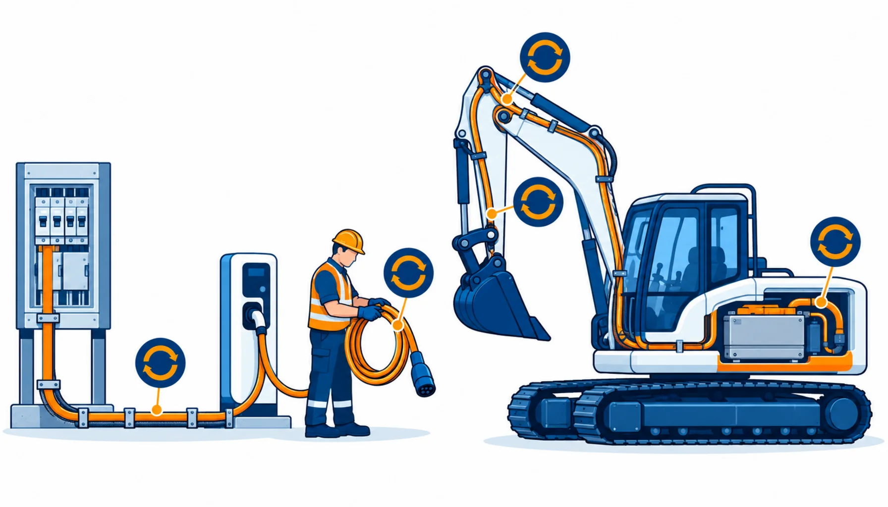
Quick Answer: Battery plant brings three new cable duties to a construction site: the charging infrastructure cable from board or transformer to the charge point, the charging cable that gets handled every shift, and the high-flex power circuits on the machines themselves. Each is selected on flex life and environment, not just ampacity. Fix the charging schedule and the machine geometry first, demand flex test evidence, and treat the charging run as infrastructure that outlives the project it was bought for.
Introduction
Electric excavators, loaders and dump trucks have moved from pilot projects into ordinary fleets, and their cable duties are different from anything else on site. The charging cable is handled daily by operators in gloves. The machine’s own circuits flex with every slew of a battery-electric boom. And the charging infrastructure is a fixed asset with a copper content that deserves a procurement conversation of its own.
Fleets that treat these as afterthoughts buy the same cable twice: once in the wrong construction, and again a season later. This guide separates the three duties and works through each.
What Electrification Changes on Site
New load shape. Chargers draw hard for hours, in blocks that follow the shift pattern, and the site distribution sees a load profile nothing else produces. Charging infrastructure sizing is a distribution question before it is a cable question.
New handling duty. Charging cables are coiled, dragged across mud, driven over and plugged in cold. The duty resembles a tool lead carried at welding-cable current.
New flex duty on the machine. Battery-electric plant runs high current through circuits that flex with the working movements, and the flex life of those circuits is a genuine design constraint.
New infrastructure lifetime. Charge points outlive projects. The cable from board to charge point is bought once and used by every machine that follows.
Charging Infrastructure: The Feeder to the Charge Point
The run from the site supply to the charge point is the biggest copper item in the electric-plant cable order, and it is sized on the charger’s draw and the route.
Size on the charger, not the machine. The charger’s continuous rating and the site’s charging schedule decide the feeder. Where several chargers share a supply, the diversity assumption is where fleets get caught: every machine back at the yard at once is a real scenario, not a design fiction.
Route and protection. Charging bays sit where plant works, so the feeder takes armoured or protected construction, routed clear of traffic, with ramps or ducting at crossings. The armoured-versus-unarmoured reasoning from ordinary site feeders applies unchanged.
Future capacity. Conduit and ducting cost little at installation and everything later. Put a spare in the ground when the first charger goes in; the fleet always grows. The same logic that sizes site supply points, covered in our note on transformers and site substations, decides whether the charging load deserves its own transformer rather than a longer low voltage run.
| Duty | What It Lives With | What to Specify | Evidence to Demand | Cost and Lead-Time Driver | How It Fails |
|---|---|---|---|---|---|
| Charging feeder, board to charge point | Fixed infrastructure, long continuous draw, outdoor | Armoured or protected construction sized on charger diversity, ducting at crossings, spare capacity in the ground | Voltage drop and load calculation, sheath and armour construction drawing | Copper-heavy; trenching and protection dominate the installed cost | Undersized feeders when the fleet grows, damage at unprotected crossings |
| Charging cable and connector lead | Handled daily, coiled, dragged, plugged cold | Fine-stranded conductor at charger current, high-flex sheath, cold flexibility, plug and inlet compatibility, length that reaches without tension | Flex cycle test at handling radius, cold-flex data, connector cycle rating | Handled cable is a consumable in practice; buy quality and standardise | Jacket cracks at the plug boot, broken strands at the inlet, connector wear |
| On-machine high-flex circuits | Flexes with every working movement, high current | High-flex power construction, flex cycle rating at machine geometry, abrasion and temperature ratings | Flex test at the machine's bend points, temperature data at the battery and drives | Machine builder territory; spare circuit stock is the buyer's lever | Conductor fatigue at moving joints, chafe at clamps, heat ageing near packs |
| DC and battery runs | High current, short runs, thermal sensitivity | Conductor sized for the dip and the heat, lugs and terminations rated for DC, separation from signal circuits | Derated ampacity at pack temperature, termination specification | Copper content and fitting discipline | Hot terminations, insulation ageing near heat sources |
The Charging Cable: A Consumable Worth Specifying
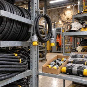
No matter what the brochure says, charging leads live a consumable’s life, and the specification should treat them that way. Fine stranding, a high-flex sheath, and cold flexibility for winter starts are the baseline; the connector’s own cycle rating matters as much as the cable, because most leads die at the boot or the inlet rather than mid-run.
Standardise across the fleet: one lead specification, one connector family, a defined length that reaches without tension, and a swap-out stock. The wider flex-life argument is the same as any handled cable, and our note on cable bending cycle life covers what the test evidence should show. Fleets that buy one generic lead for every machine carry a spares bin that fits nothing; our note on working with a high-flex cable supplier covers how to hold that standard across projects.
On the Machine: High-Flex and DC Runs
Battery-electric plant concentrates high current into circuits that move. The boom, slew and travel circuits flex at defined points every cycle, and heat from the packs and drives sits close to the cable routes. Machine builders specify these circuits, but the fleet’s leverage is in spares and replacement discipline: holding spare high-flex circuits for the duty points that actually wear, and replacing them at the first signs rather than after failure. Where machines carry automated functions, the duty overlaps with construction robotics, and our note on construction robot cable covers the moving-circuit side in depth.
The DC runs between battery, inverter and drives size like any short high-current run: on the dip, the heat and the terminations. Our note on battery cable sizing covers the method, and it applies unchanged.
Grid Connection and the Supply Point
Where the charging load justifies its own supply rather than a tap off the site board, the cable conversation moves upstream, and the decisions get more consequential.
Transformer placement. A charging bay with its own transformer keeps the heavy current short: high voltage arrives by a modest feeder, and the low voltage side is measured in metres. That is cheaper in copper and kinder to the site’s voltage than a long low voltage run sized for every charger at once.
Protection and metering. Charging feeders carry sustained load, and the protection settings, metering points and earthing belong in the same design review as the cable schedule. A feeder that trips on the fleet’s first simultaneous charge is an architecture finding, not a cable fault.
The interface clamp. One clause saves repeated arguments: the point where the utility’s or the plant supplier’s scope ends and the site’s begins. Everything past that clamp is bought, tested and recorded by the fleet, and the RFQ should say so explicitly.
Charging Bay Operations
The bay is where the cable gets used, and small operating disciplines change what the procurement buys.
Coil and store properly. Leads coiled wet and hung by the cable age in weeks. Hooks at bay height, ramps over the routes, and a coil routine that takes the bend out of the plug section cost almost nothing and show up directly in lead replacement counts.
Protect the route. The feeder crossing that plants drive over every shift needs a ramp or duct from day one. Damage at crossings is the most common infrastructure fault and the most avoidable.
Watch the first winter. Cold-flex problems announce themselves in the first cold snap, as stiff leads that operators fight. Leads that fail the cold test belong in storage, not in service, and the swap-out stock is what makes that decision free.
Battery Storage Alongside the Chargers
Sites that charge big fleets off a modest supply increasingly add battery storage to buffer the load, and the storage bay adds its own cable line: high current DC runs between packs and inverters, AC runs to the chargers, and the communication circuits that manage it all.
The DC discipline is the same as on the machines: size on the dip and the heat, keep runs short, and terminate properly, because DC terminations run hottest at the lugs. The AC side is standard feeder work with the charging profile as its load. What fleets get wrong is the communication layer: storage, chargers and the site’s energy management all talk to each other, and those circuits are noise-sensitive controls, not power. Screen them, separate them, and put their core schedule in the same RFQ as the power cable. The generation-plus-storage pattern is covered in our note on the generator and storage hybrid system, and the same architecture serves a charging bay that the grid connection cannot carry alone.
What to Freeze Before the Order
| Decision | What to State | Evidence to Attach | Cost of Leaving It Open |
|---|---|---|---|
| Charging schedule | Machines per charger, shift pattern, simultaneous draw | A charging load profile for the site | Feeders sized for a diversity that never happens |
| Feeder routes and protection | Routes, crossings, ducting, spare capacity in the ground | Routing drawing with the crossings marked | Trenching twice for a fleet that grew |
| Lead standard | One specification, one connector family, defined lengths | The standard as issued to operators | A spares bin that fits nothing |
| Flex evidence | Handling radius for leads, machine geometry for circuits | Flex cycle tests at the declared radii | Cables bought on ampacity that die on bending |
| Environment | Mud, UV, winter cold at the charging bays | Sheath and cold-flex declarations | Leads that crack in the first winter |
| Copper basis | Basis and validity window on the infrastructure order | Quotation terms naming the basis | Infrastructure priced at tender, bought a season later |
Lead Time and Cost Structure
Charging cable and leads are fast lines, typically days to two weeks. The infrastructure feeder is a construction item: one to three weeks for the cable itself, and the civils around it dominate the calendar. Order the infrastructure against the first machine delivery, and the leads against fleet standardisation, not per machine.
On cost, the feeder is copper-heavy and worth a basis clause, because charging infrastructure is designed at project stage and built when the machines arrive. Leads are recurring spend, and the savings come from standardisation and quality rather than unit price: a fleet buying one good lead specification spends less per year than a fleet replacing whatever was closest. UV-stabilised constructions for the outdoor bays, of the type covered in our note on UV resistant cable, cost a little more and last visibly longer in sun.
Incoming Inspection
Infrastructure feeder. Verify the construction against the order on a cut sample, run insulation and continuity tests before energising, and record the as-built route, because the next charger will tap into it.
Leads and machine circuits. Check leads against the fleet standard and flex a sample cold before the first winter. On machine circuits, verify the core schedule and terminations against the machine drawing before the first service swap.
When an Electric Plant Cable Specification Is Not the Answer
When the charger placement is the problem. Long feeders bought to reach a badly placed charge bay are the expensive version. Move the bay toward the supply, or step the voltage, before buying copper.
When leads die at the boot. Repeat connector failures are usually handling and storage: leads driven over, hung by the cable, or coiled wet. Racks and a swap-out routine cost less than leads.
When the machine circuit chafes at one clamp. A single worn edge kills any high-flex circuit. Fix the clamp or the edge, then re-fit.
When the fleet is about to change. Charging infrastructure outlives machines, and a connector family locked to the outgoing fleet is a stranded asset. Check the fleet plan before standardising.
RFQ Checklist
- Charging load profile: machines per charger and simultaneous draw
- Feeder routes with crossings, ducting and spare capacity noted
- Charger rating and the feeder sizing basis, with the calculation
- Lead specification: conductor class, sheath, cold flex, connector family and length
- Flex cycle evidence at the declared handling and machine radii
- UV and temperature declarations for the bays
- DC run sizing basis with termination specification
- Spare strategy: leads per bay, machine circuits per duty point
- Copper basis with validity window on the infrastructure order
- Delivery against first machine arrival, and against fleet standardisation
Conclusion
Electric plant cable is bought as three separate decisions: infrastructure sized on the real charging schedule, leads standardised across the fleet, and machine circuits specified on flex life at the real geometry. Freeze those with the order, and the charging bay stops being the site’s newest source of downtime.
Kexingyu Cable Group (KXYE) has manufactured cable in Quanzhou since 1996, including high-flex power, charging and weather-resistant constructions for electric plant and charging infrastructure, with flex test documentation and fleet standardisation support. Send us the charging schedule and the machine fleet list, and we will come back with constructions per duty, the evidence and a delivery plan. The fastest route is a request for quotation.