
Busway vs Power Cable in Data Centers: When to Use Each
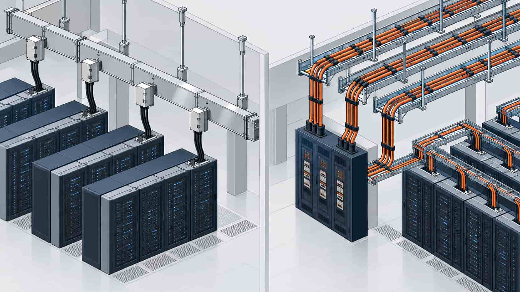
Quick Answer: Busway wins where loads change: rack rows, tap-off density and phased builds. Cable wins where circuits are fixed: long straight runs, risers, generator ties and everything outdoor or medium voltage. Most well-run data centers use both, and the design question is which distribution problem each zone really has.
Introduction
Few distribution arguments in data center design are as persistent as busway versus cable. Advocates of busway point to flexibility and installation speed; advocates of cable point to cost per ampere and proven simplicity. Both are right, which is why the question is never “which is better” but “which distribution problem does this zone have” — and the answer changes aisle by aisle.
This article compares the two on the dimensions that actually decide projects: ampacity and cost per ampere, load flexibility, installation and change-order speed, maintenance behavior, and the failure modes each carries. The context is a market where distribution equipment, like switchgear, has been subject to the same lead-time pressure we describe in the 2026 data center equipment shortage — a reality that affects both products’ delivery schedules and strengthens the case for designing with what can actually arrive.
What Each System Actually Is
Busway is a prefabricated metal enclosure housing copper or aluminum busbars, delivered in straight sections and elbows, with tap-off boxes that plug in anywhere along the run to feed a rack or PDU. Power cable distribution is the classical alternative: factory-made cable pulled on site, terminated at both ends, routed through trays and ducts from switchboard to load. One is a product you assemble, the other is a system you install — and nearly every advantage traces back to that difference.
The economics follow the same split. Busway carries a higher material cost per ampere but compresses labor and reconfiguration costs, because adding a load means plugging in a tap-off box, not pulling and terminating a new feeder. Cable is cheaper per ampere over distance but charges you in site labor every time the layout moves. In a hall where rack layouts are frozen on day one, cable’s price advantage is real; where layouts evolve with tenant demand or GPU generations, busway’s plug-in geometry pays for itself.
Where Busway Wins
Overhead busway above each rack row has become the default in colocation and hyperscale white space for good reasons. Tap-off boxes let operators add or move loads without electrical isolation of the whole row; ampacity is upgraded by swapping sections rather than pulling new feeders; and the visual, walkable overhead corridor makes inspection fast. Vertical busway risers also climb shafts efficiently, delivering multiple floors from one core penetration where a cable riser would need significant space and fire-stopping at every landing.
Busway also shortens the schedule in phased builds. A row can be energized with busway in place before its final load list exists, then populated tap by tap as racks arrive — valuable precisely in AI-era projects where the load list changes between design and installation.
Where Cable Wins
From each PDU or switchboard outward to the first distribution point, and everywhere the path is long, straight and permanent, cable is the stronger answer. Long runs favor cable strongly on cost per ampere; medium voltage feeders are cable territory outright; generator-to-ATS circuits, outdoor routes and anything crossing between buildings belong on cable with appropriate armor and sheath, choices covered in our armored versus unarmored comparison. Cable also carries no joint impedance per metre — a long busway run accumulates bolted joints, each a maintenance point that thermography must watch, while a continuous cable has none.
Cable’s other advantage is fault behavior at high ratings. Large single-core sets in parallel handle very high ampacities that busway reaches only with expensive parallel runs, and a cable system’s ampacity is verifiable from the drum test certificate rather than the assembly’s rating label. For the sizing logic behind those sets, our cable size selection guide walks ampacity, grouping and voltage drop in order.
| Dimension | Busway | Power Cable |
|---|---|---|
| Cost per ampere | Higher material cost; labor and change costs drop | Lower material cost per ampere; labor heavier at every change |
| Load flexibility | Tap-off boxes plug in anywhere along the run | New load = pull and terminate a new feeder |
| Long straight runs | Joints accumulate; cost climbs with length | Continuous runs, no per-metre joints, cost advantage grows |
| Vertical risers | Compact riser, one core penetration, fire-stop at landings | Needs tray space and multiple penetrations at height |
| Medium voltage | Not applicable | The only option; IEC 60502-2 constructions |
| Failure modes | Bolted joints and tap contacts to inspect | Terminations and route damage; screen and sheath health |
| Schedule in phased builds | Energize early, populate tap by tap | Feeders pulled as load list finalizes |
The Hybrid Reality: Both in the Same Hall
Walk a modern hyperscale hall and you will find cable doing the heavy, invisible work — medium voltage intake, transformer links, switchboard to PDU feeders, generator ties — and busway doing the flexible, visible work above the racks. The design question is the boundary: put busway where load uncertainty lives (white space rows, colocation cages, GPU aisles that will be repopulated), and put cable where the load is known and the route is fixed. Mixing them is not indecision; it is matching distribution technology to distribution problem.
The boundary also has an electrical dimension. Busway impedance differs from cable impedance, so voltage drop, fault levels and protection coordination must be calculated for the actual mix on each path — not assumed from a cable-only study. And where A/B redundant paths run overhead through the same aisle, the mutual heating rule applies to busway and cable alike, as it does in the N+1 versus 2N redundancy discussion: independent paths that share thermal space are not fully independent.
| Application | Use | Why |
|---|---|---|
| Rack row distribution, colocation | Busway | Tap-off flexibility; loads change with tenants and hardware |
| GPU/AI aisles, phased population | Busway | Energize early; repopulate as hardware generations change |
| Switchboard to PDU, long runs | Cable | Cost per ampere over distance; no joints per metre |
| MV intake and transformer links | Cable | Busway not applicable at MV; single-core sets sized to study |
| Generator to ATS | Cable | Fixed route, high ampacity, outdoor segments possible |
| Vertical riser between floors | Busway | Compact shaft use; one penetration with landings tapped |
| Outdoor or inter-building routes | Cable | Armor and sheath options; busway is an indoor product |
When "All Busway" or "All Cable" Is Not the Answer
Standardizing on one technology for its own sake fails predictably. An all-busway hall pays busway prices for long, permanent feeders and accumulates joints on routes that should be continuous cable; an all-cable hall converts every future rack change into a pulling job and clogs trays with feeders that a tap-off would have replaced. The pattern to resist is technology loyalty replacing zone analysis — both failures are expensive precisely because they are systematic.
There is also a procurement failure mode on each side. Busway bought without joint and tap torque documentation becomes a thermography program without a baseline; cable bought from a trader rather than a factory — a distinction our manufacturer versus trader checklist makes concrete — arrives without per-drum test evidence and without a factory to call when a termination misbehaves. Either way, the cheap version of the decision is paid for during commissioning. The mechanisms behind early failures, from poor terminations to route damage, are the same ones behind common cable failures, and they apply to busway tap contacts just as much.
RFQ Checklist: Pricing the Distribution Mix
- Zone plan marking busway zones and cable zones, with the boundary feeders named
- Ampacity per run and per tap position, including growth headroom
- Busway scope: straight lengths, elbows, tap-off box counts and ratings, hanger spacing
- Cable scope: constructions, cross-sections, parallel set counts, tray or duct routing
- Impedance data for both systems so protection coordination can be calculated on the real mix
- Joint and tap torque documentation requirements for busway; per-drum test records for cable
- Fire performance and LSZH requirements where routes pass through shared spaces
- Delivery schedule aligned to the phased energization plan
- Copper price mechanism for both products, since busbar and conductor track the same metal
- Warranty and after-sales response terms for joints, taps and terminations
A single supplier group that produces the cable side — from medium voltage feeders to LSZH rack feeders — and coordinates with the busway package keeps the impedance data, test evidence and delivery schedule coherent. Kexingyu Cable Group (KXYE) supplies that cable scope, with copper price linkage across the order.
Conclusion
Busway versus cable is not a war with one winner; it is a zoning decision. Busway owns the places where loads change — rack rows, colocation cages, AI aisles populated in phases. Cable owns the places where circuits are fixed and long — MV intake, PDU feeders, generator ties and every route that leaves the building. Most facilities are hybrids, and the best ones are deliberate hybrids.
Decide zone by zone, calculate the real electrical mix rather than assuming one technology, and buy each side with its own evidence: torque documentation for busway joints, per-drum test records for cable. Do that, and the distribution system disappears into the background of the facility — which is the highest compliment a power path can earn.
Recent Posts
Thermal Runaway in Lithium Batteries: What BESS Buyers Should Understand
Thermal Runaway in Lithium Batteries: What BESS Buyers Should Understand How thermal runaway starts, how it propagates, and which evidence buyers should require before approving
Energy Storage for Data Centers: A Growing Backup Power Option
Energy Storage for Data Centers: A Growing Backup Power Option Batteries have always backed up data centers in the form of UPS strings. Grid-scale BESS
YJV vs YJY: Reading Chinese Cable Designations Like a Local
YJV vs YJY: Reading Chinese Cable Designations Like a Local YJV vs YJY: Reading Chinese Cable Designations Like a Local Quick Answer: YJV and YJY