
Buying Data Center Cable Tray for High-Density Halls: Fill, Load and Lead Time
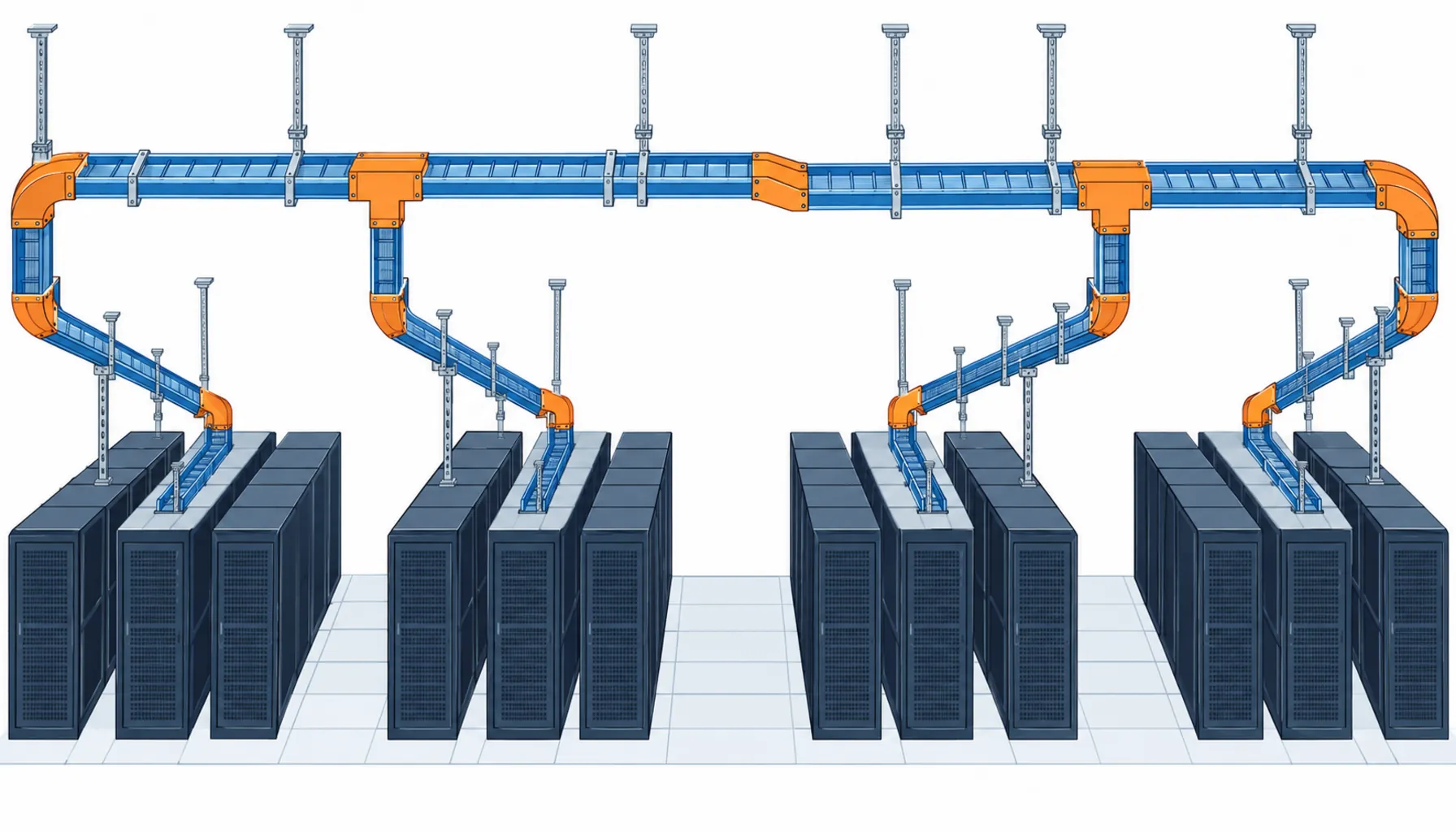
Quick Answer: Cable tray is usually under two percent of a data hall cabling package by value, and it is the first thing that stops a fit-out. The purchase that works is decided by four numbers, not by brand: the load class your span requires, the fill ratio you declare for future capacity, the coating mass on the steel, and the delivery date of the fittings rather than the straight sections. Get those four into the enquiry and the tray becomes a commodity line item. Leave them out and you will either pay for a redesign during installation or buy a tray system that cannot carry the cables the hall will run in three years.
Tray is the part of a power installation that has to be right before anything else can be installed. The structural design reserves the routes, the ceiling grid gets set around them, and the cable pulling plan assumes their geometry. Once a hall is being built, changing tray is not a material substitution, it is a sequence change, and sequence changes are what turn a four-week delivery into a twelve-week one. That is why the tray package deserves more procurement attention than its price suggests.
Introduction
Almost every delay story in a high-density data hall fit-out has the same shape. The cables arrived. The switchgear arrived in the end. What sat on site was a partial tray system, because the straight sections shipped on the standard cycle and the fittings did not. A tray run is a chain of straight lengths plus bends, tees, reducers, expansion joints and transitions, and in a dense hall the fittings can be the larger share of the line items. Suppliers quote the straight sections from stock and manufacture the fittings to order, so the enquiry that specifies only total metres has asked for the wrong half of the package.
There is a second reason to treat tray as a procurement decision rather than an installation detail. Tray is where the hall’s future capacity gets physically reserved. Fill ratio, spare routes and support spacing are all fixed at installation, and all of them are effectively irreversible once the hall is loaded. A specification that sizes tray for today’s rack count and not for the density the site is planned to reach has, in practice, decided that the hall will not be expanded. Our note on high density rack cabling covers how quickly that ceiling arrives.
The Four Numbers That Decide the Purchase
Load class. Metal tray and ladder are classified by the uniformly distributed load they carry at a stated support span. The common classifications used in specifications set working loads at 1.5 metre and 3 metre spans, so a load class on its own is meaningless without the span attached to it. This matters commercially because span drives steel thickness, and steel thickness drives both price and the number of supports the contractor installs. If the enquiry says “medium duty” and the contractor prices a 1.5 metre span, you have bought twice the support steel you needed. If it says nothing and the contractor prices a 3 metre span on a route where the structure only allows 2 metres, you have bought a tray that will deflect.
Fill ratio. Fill ratio is the share of the tray cross-section occupied by cable. It is the number that decides whether the hall can grow, because it sets how much headroom is left for the next row of racks. The limits that appear in most data hall specifications, around 40 percent where power cables dominate and up to 50 percent where signal cable dominates, come from installation guidance rather than from a wiring code, which is exactly why they get argued about during a value engineering exercise. Argue it before the order, not after: a 40 percent specification can be cut to 60 percent by a contractor looking for savings, and the consequence only becomes visible when someone tries to pull an additional feeder two years later.
Coating mass, not coating name. Hot dip galvanised is a description of a process, not a performance level. What protects the steel is the zinc mass per unit area, and it varies by process and by whether the steel was cut and drilled before or after dipping. Cut-and-weld-after-dipping leaves bare edges that rust first. For a data hall, which is normally a dry, temperature-controlled environment, the coating requirement in a specification is often stricter than the environment needs; the reason to keep it is that tray installation damages coating, and thicker zinc tolerates site damage. Where the hall has a humid, coastal or industrial exposure, the choice moves to stainless or to a non-metallic system, and the price step is significant enough to be worth confirming rather than assuming.
Fitting delivery, not section delivery. The fourth number is a date. Ask for the delivery schedule of the complete system, item by item, and not a single lead time for the package. A supplier who quotes twelve weeks and means twelve weeks for straight sections and eighteen for a special transition has quoted honestly and unhelpfully unless the schedule says so.
The Decision Table: Matching the System to the Hall
The table below compares the tray systems a buyer is actually choosing between for a dense data hall. The last three columns are the commercial ones: what the choice costs, what evidence backs it, and what goes wrong when the wrong one is bought.
| System | What to Declare in the Enquiry | Evidence to Demand | Cost and Lead Time Shape | Failure Mode If Bought Wrong |
|---|---|---|---|---|
| Perforated tray | Load class at your actual support span, width, fill ratio, coating mass in g per square metre | Load test report at the stated span, mill certificate to EN 10204 3.1, coating mass record | Fastest and cheapest in galvanised steel, 4 to 6 weeks typical; fittings add 2 to 4 weeks | Span too long for the load class gives visible deflection and cable strain at terminations |
| Ladder tray | Rung spacing, whether cables are single layer or bundled, side rail depth for the fill target | Same as perforated, plus rung spacing tolerance | Similar price to tray at equal width; more open, so easier to pull and to inspect | Bundled cables in a narrow ladder trap heat and force a derating review after installation |
| Solid bottom tray | Whether the route crosses a plenum or an air handling space, and the fire classification required | Fire test evidence for the product in that application, not a general product certificate | Higher unit price, similar cycle; often needs a shallower fill to stay cool | Buying it for thermal reasons and then filling it tightly defeats the only reason it was chosen |
| Non-metallic or FRP | The corrosion classification of the space, UV exposure, and the required fire performance | Corrosion and fire performance data for the actual resin system, plus support spacing for that material | Highest unit price, 10 to 12 weeks typical; needs its own support spacing | Reusing the steel support spacing indoors and outdoors is the most common installation error |
| Busway instead of tray | Whether the load is a fixed block of racks or a moving population, and the future tap-off plan | Short circuit rating, tap-off availability, and the delivery date of the tap-off boxes | Higher capital cost, offset by faster changes; the long pole is the tap-off boxes | Buying busway for a hall whose rack layout is still open removes the flexibility it was bought for |
Where the Tray Package Actually Goes Wrong
Three failure patterns account for most of the money lost on tray, and all three are visible in the enquiry before anything is ordered.
Fittings quoted as an allowance. An enquiry that lists metres of tray and asks the supplier to include fittings as a lump sum will get a lump sum that is either padded or incomplete. Ask for a bill of materials by item type, then check that the item count is plausible against the route drawing. A dense hall with many direction changes will have more fittings than a straight spine, and the difference is the schedule risk.
Site-fabricated bends instead of factory fittings. Cutting and bending on site is sometimes the right answer for a single awkward transition under time pressure. It is the wrong answer as a default, because site cutting removes coating at exactly the edges that rust first, and because the bend radius achieved on site may be tighter than the cable manufacturer’s minimum. Where the installation plan relies on site fabrication, the cable specification needs to state the minimum bend radius and the pulling plan needs to respect it. Our note on cable pulling tension and sidewall pressure sets out what the numbers look like in practice.
Support steel treated as the contractor’s problem. Support spacing, bracing and the fixing to structure are usually in the installation scope, not in the tray supply scope, which means the tray buyer and the support designer can each assume the other has checked the span. That is how a system rated at 1.5 metres gets installed at 3 metres. Put the span in the tray specification and put the same span in the installation method statement.
There is a fourth pattern that is not an error so much as a missed opportunity. Tray is bought as part of the electrical package and paid for by the metre, so nobody owns the question of whether the hall needs the tray it is buying. A short review of the fill ratio against the planned final rack count costs nothing at enquiry stage and is unrecoverable later.
Freezing the Right Things Before Release
Every item below is a place where an enquiry that stays silent will still receive a compliant product, and where one extra line converts a future change from a reinstallation into a variation.
| Item | What to State | Evidence to Attach | Cost of Leaving It Open |
|---|---|---|---|
| Load class and span | Working load with the support span it applies to, in writing, on the same line | Load test report at that span | Support steel added on site, or a tray that deflects under the final cable load |
| Fill ratio ceiling | The fill ratio the supplier's cross-section must support, with the design rack count behind it | Fill calculation using the actual cable outside diameters | Additional feeders re-routed over a longer path when the hall grows |
| Coating specification | Zinc mass per unit area, and that it applies after fabrication | Coating mass record plus mill certificate to EN 10204 3.1 | Edge rust at every cut, visible within the first year and in the defect list at handover |
| Fittings list | Item by item, with quantities, not as an allowance | Bill of materials matched against the route drawing | Site fabrication, with coating damage and bend radii set by whoever is on the ladder |
| Bend radius compatibility | The minimum bend radius the tray must accommodate for the largest cable | Comparison against the cable datasheet | Cable pulled round a bend it was never rated for, and a hidden defect |
| Expansion provision | Whether expansion joints are required for the run length, and at what intervals | Supplier calculation based on the temperature range | Buckling or pull-out at long straight runs after the first full seasonal cycle |
| Bonding continuity | Whether the tray is used as an equipment earthing conductor, and the continuity test to be witnessed | Continuity test record per run, signed at installation | An earthing path that has to be added after the tray is loaded and inaccessible |
| Delivery schedule | Dated delivery per item group, with the fittings dated first | Schedule as a contract annex, with a stated remedy for slippage | The hall holds cable and labour while straight sections wait for a transition piece |
When Cable Tray Is Not the Answer
Tray is the default for a reason, but there are conditions where buying it is the expensive choice.
A hall whose rack layout is genuinely undecided. If the rack population will move every year, the fixed geometry of tray becomes a constraint. Busway, or a design that keeps tray on the spine and relies on overhead drops, costs more upfront and less per change. Our note on 800V DC busway for AI racks covers what the busway option looks like at high rack power.
Routes that cross fire compartments. Here the tray is not the question; the penetration system is. Buying tray without confirming what the penetration detail will accept produces a combination that no fire stop system has been tested with, which is a compliance problem discovered by a third party at handover rather than by the design team. Our note on firestop cable penetration systems covers the interface.
Seismically active sites. Bracing changes the load path, and it changes which tray systems are practical. On a site with a specified seismic design category, the tray specification should name the bracing scheme it is designed to work with, because the alternative is a bracing design done after the tray is bought. The interface is set out in our note on seismic bracing for cable trays.
Where the volume is too small to justify the design work. A single small hall, or a retrofit of a few rows, may be better served by standard catalogue containment bought from whatever is on the shelf. Running a full load class and coating specification exercise over twelve metres of tray costs more in engineering hours than the tray itself.
RFQ Checklist
Send these to the supplier and the installer, and require the same numbers back from both.
- Load class with the support span it applies to, stated on the same line of the schedule
- Width and side rail depth, with the fill calculation that justifies them against the design rack count
- Fill ratio ceiling you will hold the installer to, in writing, with the date it will be checked
- Material and zinc mass per unit area, applied after fabrication, for the environment you are in
- Bill of materials by item type: straights, bends, tees, reducers, expansion joints, transitions, couplers
- Dated delivery per item group, with fittings ahead of or alongside the straight sections
- Minimum bend radius the tray must accommodate for the largest cable in the run
- Support spacing and bracing scheme, and who is responsible for the fixing to structure
- Whether the tray is used as an earthing conductor, and the continuity test that will be witnessed
- Maintenance and inspection reaches: how the installer will access the tray after the hall is loaded
- Documentation to be delivered: as-built route drawing, item list, coating and material certificates, continuity records
- Warranty terms covering coating performance and site-damaged sections, with the touch-up method approved in advance
Conclusion
Cable tray is priced like a commodity and behaves like a critical path item. The four numbers that decide whether the purchase works are the load class at your actual span, the fill ratio you declare for the hall’s final density, the zinc mass on the steel after fabrication, and the delivery date of the fittings. Each of them costs little to specify and nothing to leave open, and each of them is expensive to discover during installation.
Kexingyu Cable Group (KXYE) supplies the cable that goes into these routes alongside the distribution equipment that feeds them: fire resistant cable and instrument cable from the special wire and cable range, the WDZ-YJY, WDZN-YJY, BTTZ, BBTRZ, NG-A (BTLY), KVV and YJV ranges used across data halls, and the GGD power distribution cabinet and KYN28 medium voltage switchgear that feed them. Send the route drawing with the rack count the hall is planned to reach and the voltage you intend to energize at, and we will return a cable and containment schedule that holds the fill margin rather than consuming it; the fastest route is a request for quotation.


