
Cable for CNC Machines: What Moving Axes Demand From Wiring
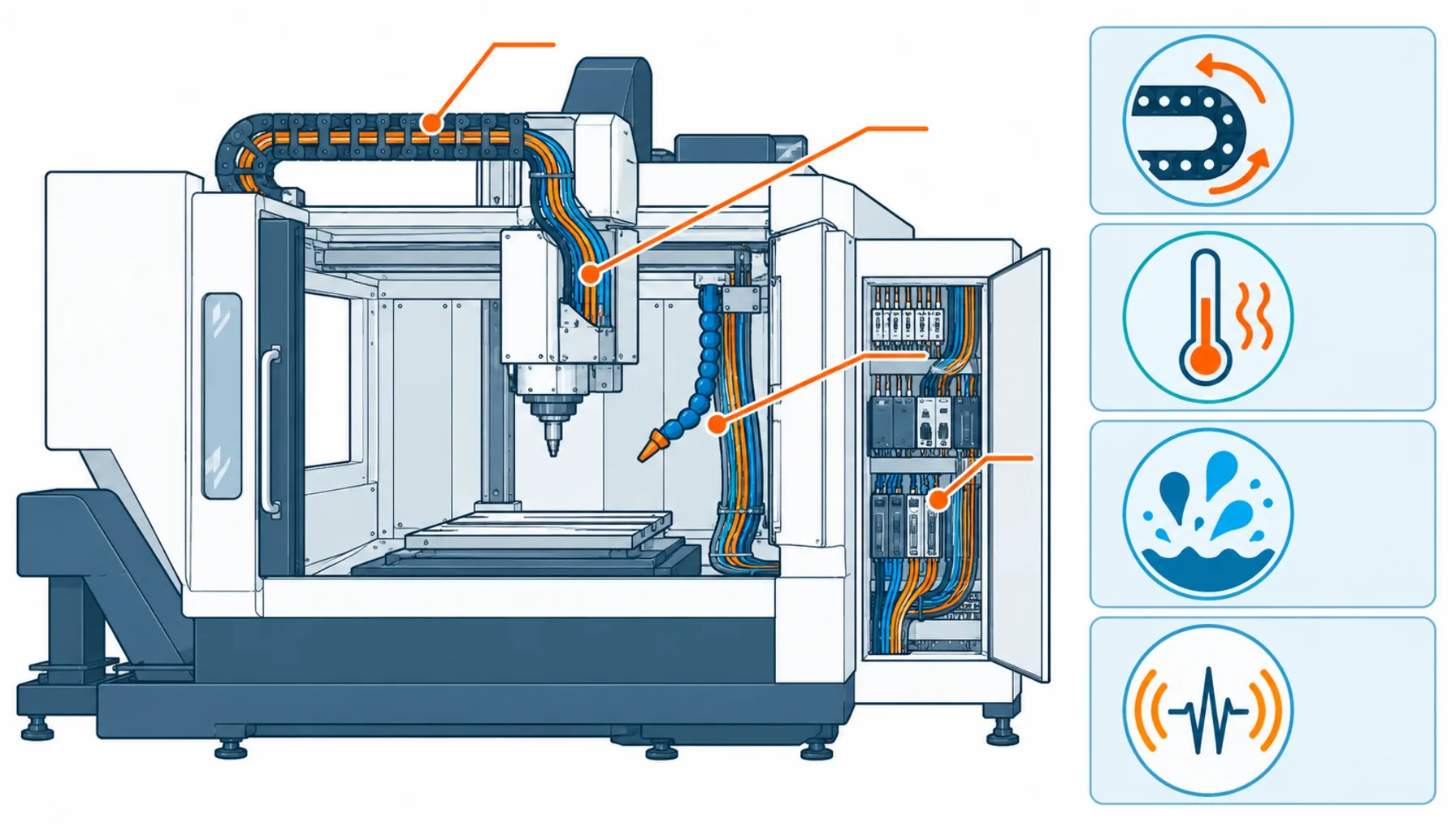
Quick Answer: A CNC machine puts its wiring through constant axis bending, spindle heat, coolant splash and electrical noise — so every cable family inside needs motion-grade construction matched to its own duty.
Open the side panel of any CNC machine that has run for a few years and you can read its history in the wiring. The cable chain shows wear where the axis reverses hardest. A jacket near the spindle head is stained dark with coolant. Somewhere in the enclosure, a coil of spare signal cable sits coiled next to a drive because an encoder line failed intermittently and nobody trusted it again. Machine tools are compact, violent electrical environments: axes slam through reversal cycles all day, the spindle cooks its own harness, and cutting fluid finds every routing mistake. This guide maps each cable family inside a CNC — axis power, feedback, spindle, control, and the ancillary wiring — against the duty it actually sees, and lists the specification checks that separate machines that run for fifteen years from ones that visit the service bay every quarter.
Introduction
A CNC machine is a motion system wearing a metal enclosure. Three to five axes reverse at speed thousands of times an hour; the tool changer snakes its harness through a cam path on every tool call; the spindle carries high-frequency power into a rotating mass. Everything electrical on the machine moves, heats, or both — and the wiring harness is the one component that touches all of it. The builder who treats cable as a commodity discovers the cost on someone else’s production floor, usually as an axis fault alarm at 2 a.m. with a batch of parts half-finished in the fixture.
The electrical side is just as demanding. Servo drives switch hard, which makes the whole enclosure a noise environment for the feedback signals that close the motion loop — the same power-versus-signal tension documented in control versus instrumentation cable, compressed into a cabinet the size of a refrigerator. And because machine tools are sold across borders into plants with different supply standards, the wiring inside has to satisfy the machine’s certification as a system, not just its datasheets one cable at a time.
The Cable Families Inside a Machine Tool
Each family inside a CNC sees a different mixture of motion, heat and noise. Specifying them as one harness quote hides the differences that decide lifespan.
| Family | Where It Runs | Duty It Sees | What Fails First in Cheap Versions |
|---|---|---|---|
| Servo axis power | From drive cabinet through the cable chain to each axis motor | Millions of chain bend cycles; PWM ripple; acceleration shocks | Strand fatigue at the chain exit; insulation damage at dividers |
| Encoder and feedback | Same chain as the power cables, centimeters away | Continuous flexing plus the machine's full noise environment | Braid shield rupture — position faults that come and go |
| Spindle and tool changer | Fixed run to the spindle head; cam path on the tool changer | Heat soak near the spindle; high-frequency drive content; tool-call flexing | Jacket hardening near the spindle; conductor break at the changer cam |
| Coolant-side ancillaries | Chip conveyor, coolant pumps, through-spindle coolant lines | Splash, swarf abrasion, chemical exposure on the jacket | Jacket swelling or cracking from cutting fluid contact |
| Control and I/O | Enclosure to door interlocks, tool sensors, lubrication and pneumatics | Vibration, door-flex cycles, occasional coolant mist intrusion | Core breakage at glands; connector contamination from mist |
Axis Wiring: The Chain Is the Duty
The cable chain sets the rules for everything that rides in it. A machining center’s X axis may travel a meter per part and reverse thousands of times per shift, which puts the chain cables through millions of bend cycles a year — the same fundamental duty described in the drag chain guide, with machine-tool specifics stacked on top. Chain fill and divider layout matter here because machine tools pack power and feedback cables into tight cross-sections; an overfilled chain runs hot and abrades its own contents at every divider crossing. Bend radius at the chain entry, strain relief at both ends, and honest speed data in the specification are the three inputs that determine whether axis wiring lasts the machine’s life or dies in month nine.
Drive technology shapes the electrical side. Servo drives chop DC into high-frequency PWM, and the motor leads see steep voltage edges that stress insulation and radiate noise into everything nearby — a smaller-scale version of the drive-cable physics behind the VFD and soft starter comparison. Shielded, symmetric constructions with braid coverage keep the emission contained; sizing conductors with headroom for the drive’s peak currents keeps the heating manageable. Undersized axis cables do not fail dramatically — they run warm for years and quietly age everything in the chain with them.
Spindle and Feedback: Heat and Noise at the Same Time
The spindle harness lives in the machine’s hottest microclimate. Heat radiating from the spindle cartridge and its drive hardens ordinary PVC jackets over a couple of years until they crack at the first serious flex; compounds rated for continuous heat hold their temper instead. The tool changer adds a mechanical wrinkle — its harness flexes through a fixed cam path on every tool call, and that path concentrates all the bending at the same few centimeters, which is where conductor breaks appear when the cable was not chosen for the cycle count.
Feedback cables deserve their own paragraph in any CNC specification, because they carry the signals that make the machine accurate. An encoder line with a cracked shield does not fail cleanly — it injects just enough noise into the position loop to cause occasional surface-finish defects, axis following errors that vanish on reboot, or alarm codes that scatter across the week. Maintenance teams then spend days swapping drives and re-homing axes when the root cause is a few centimeters of broken braid at the chain exit. Motion-grade braid shields, correct separation from power runs and single-point grounding are cheap insurance against the most expensive diagnostic rabbit hole in machine tools, a pattern familiar from the failure-mode catalog.
The Environment Around the Enclosure
Outside the cabinet, the machine fights coolant and swarf. Cutting fluid attacks the wrong jacket compounds — swelling some, embrittling others — and abrasive chips sand soft jackets thin where cables run near the chip path. Pumps, conveyors and through-spindle coolant systems need jackets selected for chemical contact, not just flexibility. Inside the enclosure the enemy is heat and mist: enclosure temperature rises with duty cycle, and oil mist works into connectors that are not sealed. Builders who read their own service records will find that a surprising share of electrical service calls trace to jacket or connector degradation in exactly these zones — which is why the environment rows in a datasheet review deserve as much attention as the electrical ones.
One more environmental factor is invisible: electromagnetic compatibility as a system requirement. Machine tools ship with CE marking or equivalent, and the EMC performance behind that marking is achieved or lost in the wiring — shield continuity, gland quality, separation discipline and cabinet layout. A builder who reworks the harness to pass EMC after the fact is reworking decisions that belonged in the cable specification.
| Check | What to Pin Down | Why It Decides the Outcome |
|---|---|---|
| Axis duty | Travel, reversal rate, acceleration and rapid speeds per axis | Sets chain cable flex life and bend radius requirements |
| Chain layout | Inner radius, fill plan, divider positions, weight distribution | Overfilled chains abrade and cook the cables inside them |
| Drive electricals | PWM frequency, peak currents, cable lengths, shielding plan | Insulation stress and EMC outcomes are decided here |
| Spindle climate | Enclosure temperature near the spindle, heat soak duration | Jacket compound choice follows the hottest point, not the average |
| Coolant contact | Which cables can be splashed, with which fluid, how often | Chemical compatibility is a jacket decision, not a cleanup task |
| EMC and certification | Shield continuity plan, gland spec, machine-level EMC test route | Machine certification is earned in the wiring, not the brochure |
When Machine-Tool Wiring Rules Are Not the Answer
Honesty about scope keeps this guide useful. The rules here address wiring that lives inside the machine — chains, spindle harnesses, enclosure I/O. They do not cover the installation feeding the machine: the feeder from the shop’s distribution board, the supply-side protection and disconnects, and the grounding electrode system are building electrical work governed by local code and the plant engineer of record. Robots integrated alongside CNC machines in the same cell follow vehicle-arm cabling practice rather than machine-tool practice. And cabinet engineering — drive layout, thermal design, the discipline described in custom control cabinet building — is its own specialty that the harness depends on but does not define. Know which layer each decision belongs to.
RFQ Checklist: What to Send the Cable Supplier
Put the machine’s real duty in writing before quotes come back:
- Axis data per axis: travel, rapid speed, reversal cycles per hour, chain geometry and fill plan
- Drive data: servo and spindle drive models, PWM content, cable lengths, shielding requirements
- Spindle climate: measured enclosure temperatures near the spindle at full duty
- Coolant exposure map: which harness sections can be splashed, and with which fluid
- Feedback circuits: encoder and scale signal types, separation and grounding requirements
- Certification target: EMC and machine safety marking the wiring must support
- Proof and spares: flex test data, batch traceability, spare harness sets for critical axes
Conclusion
A CNC machine asks its wiring to bend with every part it cuts, to shrug off heat and coolant, and to keep position signals clean in a cabinet full of switching noise. Machines that get motion-grade axis cables, heat-rated spindle harnesses and properly shielded feedback lines run for decades between electrical overhauls; machines that get catalog cable run on their error logs instead. The difference is specification discipline, not luck.
Kexingyu Cable Group (KXYE) supplies motion and machine-tool cable constructions to builders who need each family matched to its duty, with batch traceability and flex data behind the ratings. Send your axis duty and enclosure layout through the RFQ page, and we will quote the harness by family — with the checks above built into the offer.


