
Data Center Cable Lifecycle: Planning Replacement Before Failure
Quick Answer: Power cable is designed for decades but fails at projects, water and terminations — lifecycle planning means knowing the failure modes and replacing on your calendar. Cable is the longest-lived equipment in a data center and the least observed. Servers are replaced on three-year cycles with dashboards watching every metric; the feeders that keep those servers alive are inspected when something smells warm. That asymmetry is why cable failures in mature facilities so often trace back to conditions that were visible — and measurable — for years before the outage.
Introduction
Lifecycle planning for cable inverts the usual procurement reflex. The question is not only what to buy and how much, but what the cable will experience across twenty or more years of service: thermal cycling, moisture, mechanical disturbance during every adjacent works, and the slow accumulation of small installation defects into one bad day. A facility that understands those mechanisms can watch for them with inexpensive monitoring and replace a route on its own schedule, during planned windows, rather than during an incident.
This article works through the lifecycle in order: what design life actually promises, how cable really fails, what condition monitoring can see, how to schedule replacement around the data center’s own refresh rhythm, and what documentation makes the whole program auditable. The insulation chemistry that sets design life — and why XLPE dominates — is explained in our guide to XLPE cable, and the equipment rooms these cables serve are covered in our data center power collection.
What Design Life Actually Promises
XLPE power cable is engineered for a 25-40 year service life at its rated 90 °C continuous conductor temperature — and that rating is a promise about chemistry, not about your building. The promise holds when the cable runs cool, dry, undisturbed and correctly terminated. It erodes when any of those conditions drift: sustained overload or a hot tray pushes thermal aging faster, water in a duct attacks the sheath and then the screen, and every adjacent construction project is an opportunity for mechanical damage that shortens life by decades in one afternoon.
The practical implication is that design life is a distribution, not a date. Two identical cables in one facility can differ by twenty years of remaining life depending on their route, their loading history and the works that happened around them. Lifecycle planning therefore treats each route as an asset with its own history file — load records, test results, incident notes — rather than applying one blanket replacement age to the whole building.
| Failure Mode | Where It Strikes | Early Sign | Detection Method |
|---|---|---|---|
| Thermal aging | Overloaded routes, hot trays, poor terminations | Rising termination temperature under load | Annual IR thermography under load |
| Water ingress | Duct runs, basements, outdoor trenches | Sheath damage history; damp ducts | Sheath integrity test; insulation resistance trend |
| Termination fatigue | Gland plates, lug connections, vibration | Discoloration, torque loss at lugs | IR scan plus scheduled re-torque |
| Mechanical damage | Routes near works, cable management churn | Any unrecorded disturbance | Permit-to-work discipline plus post-works testing |
| Insulation degradation (MV) | Long service, water trees, partial discharge | PD activity under test voltage | Periodic partial discharge measurement |
| Screen and earth corrosion | Buried or damp sections | Rising earth resistance readings | Screen continuity and earth loop tests |
Condition Monitoring: What Is Worth Watching
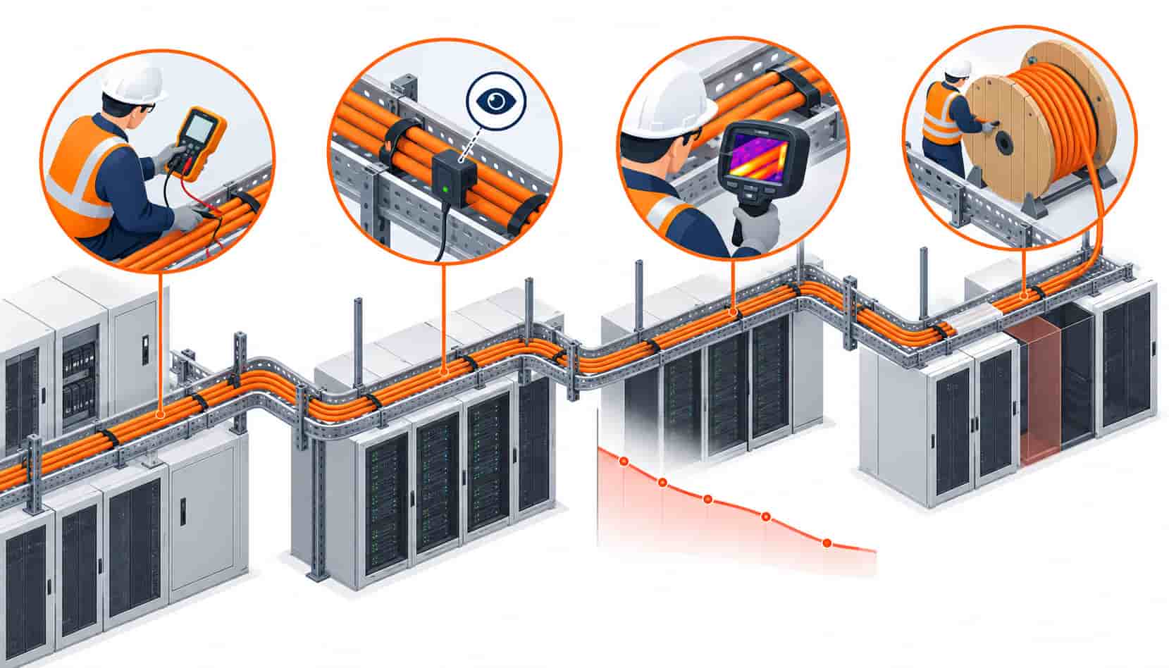
Two measurements carry most of the value in a cable monitoring program, and both are inexpensive relative to the downtime they prevent. Infrared thermography under load finds the hot spots — terminations running warm, trays with restricted airflow, the one lug that a contractor left under-torqued three refits ago — and should run annually on all distribution boards, with denser coverage on the UPS chain. Insulation resistance trending, taken at every opportunity the circuit is de-energized, turns aging into a graph: a route whose readings decline year over year is announcing its replacement window in advance.
Medium voltage routes earn two more tests. Sheath integrity testing finds water and damage in the outer jacket before it reaches the screen, and periodic partial discharge measurement on MV cable finds insulation degradation while it is still a data point rather than an event. Facilities running generator plants and long MV feeders — where one route failing means the backup chain itself is compromised — usually find these tests cheap insurance on exactly the routes whose failure costs the most. The battery side of the UPS chain deserves the same attention for different reasons; its failure patterns are treated in our guide to UPS battery problems.
Scheduling Replacement Around the Refresh Rhythm
Data centers already live on a refresh calendar: IT hardware on three to five years, electrical equipment maintenance on annual cycles, facility upgrades sequenced into low-load windows. Cable replacement planning slots into that machinery rather than fighting it. The practical pattern: classify routes by criticality and condition, group the replacement candidates by the windows their loads can tolerate downtime, and execute in planned phases with temporary supplies engineered like the permanent ones.
Two disciplines make the program real. First, records: every route’s history file — commissioning tests, thermography images, IR trends, works disturbances — is what converts monitoring from data into a replacement decision. Second, procurement timing: replacement cable is ordered against the same standards and the same quality gates as new-build, with batch test reports and factory verification, because a replacement program is exactly the wrong moment to admit a lower tier of supplier. The vetting discipline is the same one detailed in our guide to vetting Chinese electrical equipment manufacturers.
| Program Element | Recommendation | Cadence |
|---|---|---|
| IR thermography under load | All boards; dense coverage on UPS chain and terminations | Annual, plus after any major works |
| Insulation resistance trending | Log at every de-energized opportunity; graph year over year | Every maintenance window |
| MV sheath integrity test | All duct and trench routes with water exposure history | Every 3-5 years |
| MV partial discharge survey | Long MV feeders and aging populations | Every 3-6 years |
| Re-torque and termination inspection | High-vibration locations: generator rooms, UPS rooms | Per maintenance schedule |
| Route history files | One record per route: tests, images, incidents, works | Continuous; reviewed annually |
When Cable Replacement Is Not the Answer
Not every warm spot or declining trend justifies pulling new cable. Many thermography findings are termination problems — a re-torqued lug, a cleaned contact, a re-made gland — and the correct response is a repair at the connection, not a route replacement. Overheating caused by load growth is likewise fixed by load rebalancing or an added feeder, not necessarily by renewing the original route. The lifecycle program exists to distinguish these cases cheaply: monitoring tells you which routes are aging, which are overloaded and which simply have a bad lug.
The opposite error is just as costly: treating an aging MV population as fine because it has not failed yet. Partial discharge activity on a twenty-year-old feeder is not a data point to file; it is a replacement window to schedule. The whole value of lifecycle planning is acting while the decision is still yours — and the facilities that fail this test are the ones that never started measuring.
RFQ Checklist: Ordering Replacement Cable
Replacement orders deserve the same specification rigor as new-build, plus the operating history — and the certification paperwork that should accompany the batches is summarized in the power cable certifications checklist:
- Condition survey summary per route: load history, test trends, incident records
- Original specifications and standards, with editions, for like-for-like renewal
- Any upgrades decided: sheath class, fire category, cross-section corrections
- Shutdown windows per phase, with temporary supply arrangements noted
- Drum lengths matched to existing containment and pulling constraints
- Batch test reports and marking requirements for traceability into the history file
- Delivery phased to the replacement calendar, not one bulk drop
- Copper price linkage covering the phased delivery window
- Termination kits and accessories matched to existing equipment
- Documentation formatted to drop into the route history files
Conclusion
Cable lifecycle planning is the difference between a facility that replaces cable on its calendar and one that replaces it at 2 a.m. Design life is a promise conditioned on your building’s behavior; the failure modes are known, measurable and mostly cheap to watch; and a program of thermography, resistance trending and honest route history files converts cable from the last unobserved asset into a managed one.
Whether you are renewing an aging population or building the monitoring baseline for a new one, Kexingyu Cable Group (KXYE) supplies replacement scopes with the same batch documentation and copper price linkage as new-build orders — phased to your maintenance calendar, documented to drop straight into your route files.


