
Sensor and Instrumentation Cable in Dynamic Runs: What Changes vs Static Installation
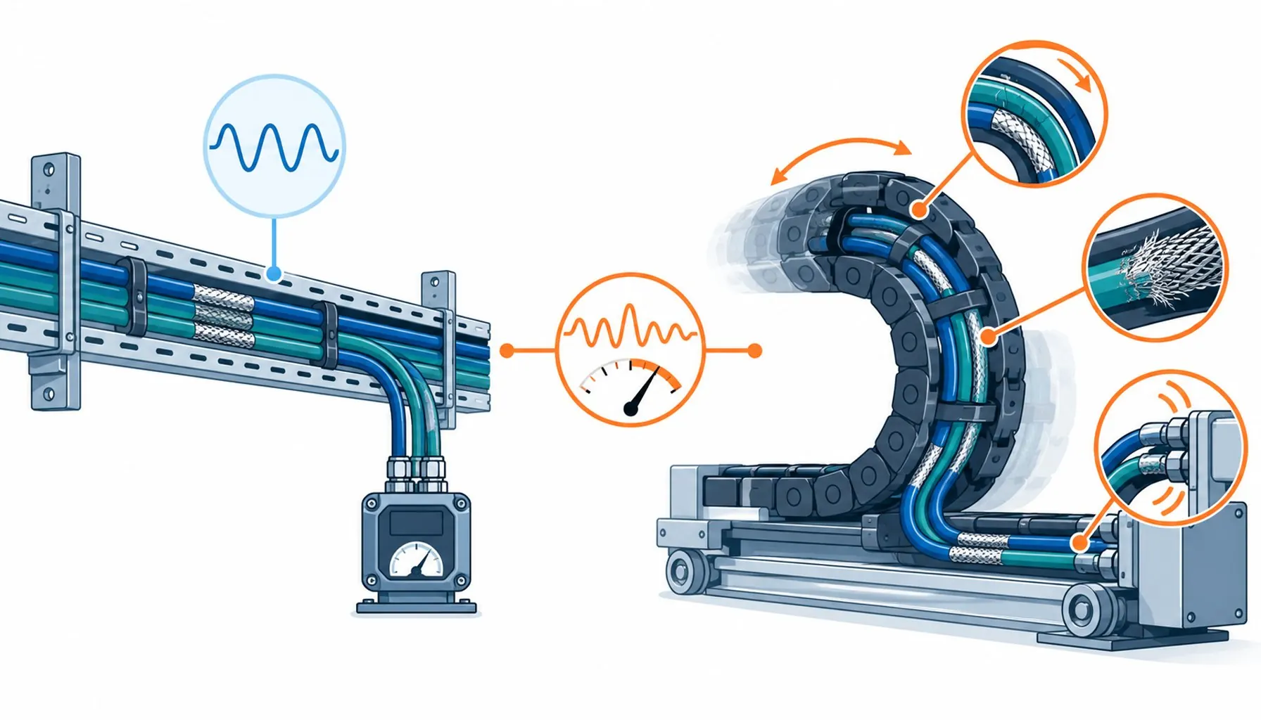
Quick Answer: Motion changes instrumentation cable from a routing problem into a fatigue problem: pairs, shields and terminations must be flex-rated, and the analog signals most sensors carry are the least forgiving loads on the machine.
The rules for instrumentation cable are written, in most references, for a cable that never moves: separate it from power, shield it, land it carefully. Then the sensor gets mounted on a moving axis, and every one of those rules survives while a new set appears that the static references never mention. The pairs must now survive bending, the shield must now survive flexing, the terminations must now survive vibration, and the signals, millivolt analog levels from thermocouples and bridge sensors, become the most fragile cargo on the machine. This guide covers what changes when instrumentation goes dynamic: the construction differences, the signals that define the difficulty ceiling, the routing law of moving machines, and the verification that keeps a dynamic sensor run honest for years.
Introduction
Factories fill with moving sensors: proximity and position sensors on actuators, temperature probes on rotating equipment, strain and load cells on moving arms, level and flow sensors on mobile equipment. The cables connecting them start life as instrumentation practice and end life as motion-cable duty, and the gap between those two descriptions is where dynamic sensor failures live. A sensor cable built to static standards survives installation testing and then dies by fatigue, pair by pair, in a chain it was never built for.
The foundation of what instrumentation cable is, its pair construction, shielding conventions and separation rules in the static world, is established in the guide to control versus instrumentation cable; this article assumes that ground and covers only what motion adds.
What Motion Changes, Layer by Layer
The conductors change first: dynamic sensor cable uses fine-stranded, flex-rated cores, because solid or coarse conductors work-harden and fracture under bending, and instrumentation conductors are among the finest on the machine to begin with. The pair twist changes: it must hold its geometry through millions of bends, which means consistent short-lay twisting and pair bonding where duty demands. The shield changes most: a foil shield that performs adequately in a tray cracks within weeks in a chain, and dynamic runs need dense braid or braid-plus-foil constructions engineered for flexing. The jacket changes: PUR or flex-grade compounds that tolerate the abrasion of carriers and the chemistry of the machine, replacing the PVC defaults of the tray world. None of these changes is optional at meaningful cycle counts.
The Signals: Why Analog Sets the Difficulty Ceiling
Discrete sensor signals, a proximity switch that changes state, tolerate a lot; noise has to exceed thresholds before anyone notices. Analog signals tolerate nothing of the sort. A thermocouple delivering microvolts per degree, an RTD bridge, a load cell output of a few millivolts full scale: noise that is invisible on a discrete input becomes a drifting, wandering measurement on these, and the drift looks like sensor failure, process change or calibration loss rather than cable trouble. The design consequences stack: individual shielding around the analog pairs, strict separation from power runs, attention to where the shield lands at each end, and grounding architecture that does not invite ground loops into a microvolt measurement.
Digital bus signals sit between the extremes: tolerant of noise in the short term, but corrupted by shield degradation that grows over time, and worth protecting with the same rigor as analog when the data matters. The datasheet-audit habits from the guide to reading equipment datasheets critically apply when comparing candidate cables for these duties, because shielding claims without test conditions are common in this segment. The protection requirement each signal family brings compresses into the table below, which doubles as the construction checklist for mixed-signal harnesses.
| Check | Method | Pass condition | What failure indicates |
|---|---|---|---|
| Pair integrity | Continuity and insulation test per pair, at multiple machine positions | Stable across positions and over time | Conductor fatigue in the moving section; locate the bend zone |
| Shield continuity and bonding | End-to-end shield resistance, both ends, machine moving | Low, stable, position-independent | Braid fatigue or a working clamp; trend it per run |
| Analog noise floor | Log the measurement value with the machine running versus stopped | No running-versus-stopped difference | Motion-correlated coupling; check separation and shield first |
| Reading drift | Compare against a reference sensor at intervals | Agreement within tolerance over months | Progressive cable degradation masquerading as calibration loss |
| Termination condition | Open ends at service: torque, ferrules, shield clamps | Tight, clean, geometry preserved | Vibration working the ends; re-terminate before it faults |
| Routing integrity | Walk the run: dividers, radius, service loops intact | As designed | Migration and rub points forming; fix geometry, not symptoms |
Routing Law for Moving Sensor Runs
Motion routing has a small set of laws that generalize across machines. Separate power from signal, in the carrier with dividers, in the tray with distance, and at right angles wherever crossing is unavoidable, the same separation logic that plant-wide power distribution practice applies at every scale. Respect the bend radius at the tightest point, which is usually at the sensor mount or the exit gland, not in the middle of the run. Give the moving end a service loop so the designed flex zone does the flexing, not the connector. Never clamp a cable where it bends. Keep the run out of chip paths, splash zones and heat, the same environmental logic any machine harness follows. And label and support the static end as carefully as the dynamic one, because a tidy chain feeding a tangled tray wastes the whole discipline.
The frequency of failures traced back to routing rather than cable, and the broader catalogue of causes, sits in the standard review of why cables fail, worth a read before the first dynamic run is installed rather than after the first failure.
Termination and Verification on Dynamic Runs
Terminations on moving sensor cable carry vibration duty that static terminations never see: screws loosen, crimps relax, shields work their clamps. The practices that hold up are strain relief separated from the electrical connection, shield termination that preserves 360-degree contact rather than a pigtail, ferrules on fine strands, and enough slack at every end that the machine’s motion never reaches the terminal as tension. Verification continues past commissioning: shield continuity, pair integrity and, for analog runs, the noise floor of the measurement itself, trended over time.
The table below collects the verification into a maintenance-grade procedure, ordered as a methodical visit would run it.
| Signal family | Noise tolerance | Construction requirement | Failure mode when underprotected |
|---|---|---|---|
| Millivolt analog (thermocouple, bridge) | Minimal | Individually shielded pairs, strict separation, designed shield landing | Drift that masquerades as calibration loss |
| Standard analog (4-20 mA, 0-10 V) | Low | Shielded pairs, separation from power runs | Offset and noise on the loop, intermittent faults |
| Discrete sensor signals | Moderate | Flex-rated cores, grouped shield acceptable | Conductor fatigue stops the input, not noise |
| Serial buses and fieldbus | Moderate, retries mask degradation | Bus-grade pairs, braid shielding, controlled geometry | Rising retries and dropouts as the shield ages |
| Safety-related signals | Strict, with integrity obligations | Dedicated pairs, documented separation and shield practice | Integrity of the safety function becomes unprovable |
When Dynamic Instrumentation Rules Are Not Enough
Honest limits: some sensor environments defeat cable practice entirely. Extreme temperature at the sensing point, radiation, immersion and high-vibration positions on rotating machinery sometimes belong to specialized sensor constructions or non-electrical transmission, and no amount of flex-rated jacketing changes that. Very long analog runs raise grounding and loop design questions that the cable specification supports but does not decide. And some drift problems are genuinely process or sensor problems, where the disciplined verification above is what proves the cable innocent. The dynamic rules extend static instrumentation practice; they do not replace the engineering judgment that decides whether an electrical run belongs in a given position at all.
RFQ Checklist: Specifying Sensor Cable for Moving Runs
Bring the motion to the supplier in specifics:
- Signal inventory: analog, discrete and bus signals carried, with their sensitivities
- Motion duty: radius, cycles per day, travel speed, and the position of the tightest bend
- Environment: fluids, temperature, abrasion and crush points along the run
- Separation context: what power runs share the carrier or path
- Evidence required: flex-cycle data with pair continuity and shield condition at end of test
- Termination hardware: glands, ferrules and shield clamps matched to the flexing duty
Conclusion
Motion turns instrumentation cable from a static routing exercise into a fatigue discipline: fine flex-rated pairs, shields engineered to survive what they intercept, terminations built for vibration, and routing that keeps the machine’s power and motion away from the smallest signals it carries. The analog measurements at the end of these runs set the standard, because they are the signals least able to complain until they are wrong. Specify the dynamic case deliberately and moving sensors stop being the unreliable part of the machine.
Kexingyu Cable Group (KXYE) builds flex-rated sensor and instrumentation cable with individually shielded pairs and motion-grade jackets, with flex-cycle evidence that includes the pairs and the shield. Send your moving sensor duty through the RFQ page, and we will rate the run for the motion it will actually see.


