
Procuring Cable and Shielding for EMI in High-Density Data Halls: Sources, Coupling and What to Specify
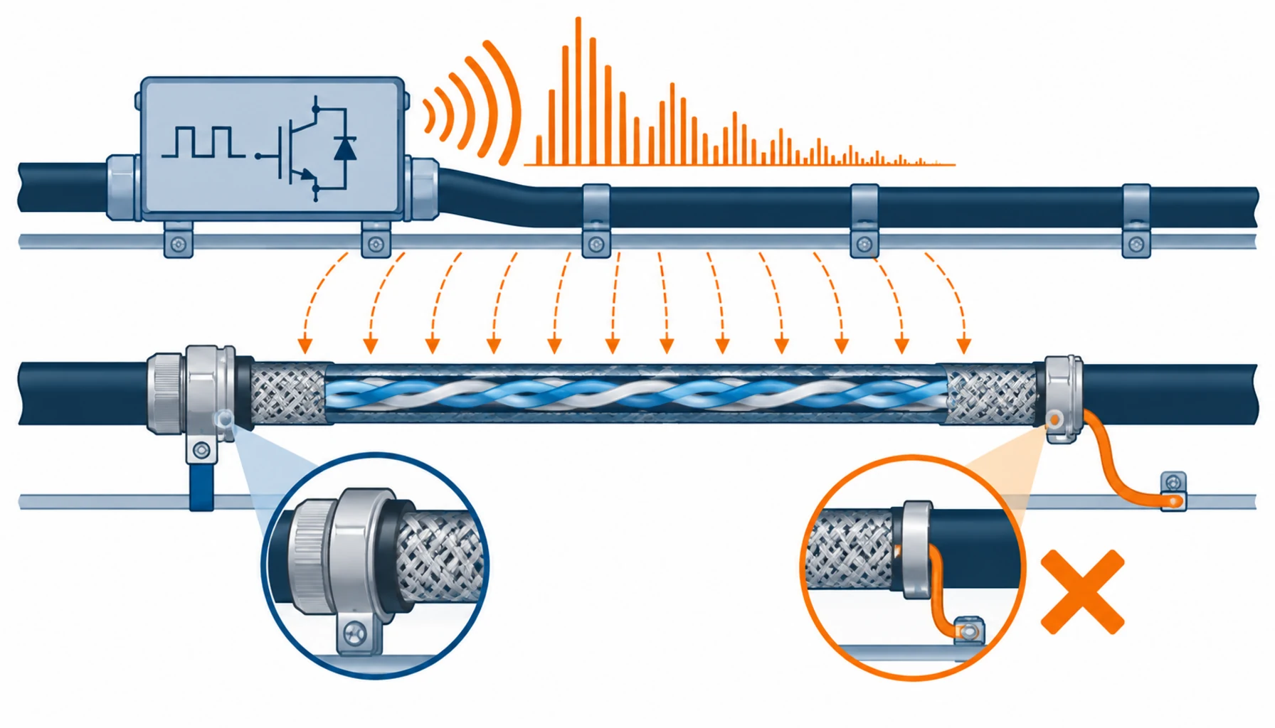
Quick Answer: Electromagnetic interference in a dense data hall is a purchasing problem that presents as a commissioning problem. The specification has to name the shield construction, the termination method and the separation distances, because those are the items that decide whether the noise path exists at all. Two of them are usually missing, and the screen termination is the one that gets done wrong on site even when it was specified.
Introduction
A high-density hall concentrates three things at once: more power switching per cubic metre, more cable per tray, and longer runs sharing the same route. Each of those raises the amount of interference present and lowers the distance between the source and the victim.
The consequences show up as intermittent faults rather than as failures, which is what makes them expensive. A network link that drops occasionally, an analogue signal that drifts, a monitoring channel that reads high during a switching event. This note deals with the cable and shielding side of that problem in halls that are dense and power heavy, and it complements our notes on EMC and grounding for moving cables and on shielded connectors and EMC, which cover the moving and connector ends of the same subject.
Where the Interference Comes From and How It Travels
Four sources dominate in a modern hall, and they couple in four different ways.
Switching power conversion. Rectifiers, inverters and the DC converters used at rack level switch at high frequency, and the faster the switching edge, the broader the spectrum it produces. Wide bandgap devices have made this worse rather than better, because their edges are faster and their emissions extend further up the frequency range.
Contactors and switching events. A mechanical switching operation produces a burst of broadband noise, which is why intermittent faults correlate with equipment operations rather than with a steady load.
Conducted coupling. Noise travels on conductors, including the earth conductor, which is why grounding practice and shielding are part of a single subject rather than two. A common mode current on an earth conductor will find any screen that is bonded to it.
Radiated and capacitive coupling. Adjacent cables running in parallel share an electric and magnetic field. The longer the parallel run and the closer the spacing, the more of the noise is transferred, so route geometry is a design input and not a detail.
The Decision Table: Four Mitigation Measures and What Each One Buys
The measures below are cumulative. The cheapest one is geometry, and it is the one most often left to the installer.
| Measure | What You Are Buying | What to Specify | Evidence You Should Receive | Cost and Effect |
|---|---|---|---|---|
| Shielded cable | Signal and control cable with a screen of stated construction and coverage | Screen type and coverage, transfer impedance where relevant, and the pair or overall construction | Type test data for the screen, and construction details for the assembly | Modest cable premium; the cost sits in the termination labour, not the cable |
| Screen termination method | The means of bonding the screen to the enclosure or the reference at each end | Three hundred and sixty degree termination, gland type, and where the screen is bonded | Termination instructions, and inspection of the first installations | Cheap when specified, expensive when improvised; a pigtail connection wastes most of the shield |
| Route separation and geometry | Physically separate trays, dividers, spacing rules and the avoidance of long parallel runs | Minimum separation distances, tray arrangement and the crossing rules to be applied | Route drawings showing separation, and inspection records at installation | Cheap in material, demanding in coordination; the first measure to be traded away under pressure |
| Filtering and reference bonding | EMI filters, common mode chokes and a bonded reference network for the hall | Insertion loss required, bonding conductor sizes and the bonding topology | Filter test data and bonding continuity measurements | Component cost plus a design effort; treats the source and the reference rather than the victim |
What Each Measure Changes in the Order
Four items convert into specification text, and three of them are commonly omitted.
Shield construction becomes a defined product. Coverage percentage, screen material and whether the screen is overall or per pair all change performance, and a description such as shielded is not a specification. Where the circuit is sensitive, the relevant figure is transfer impedance rather than a marketing claim. Ranges built for high frequency data transmission are described in our notes on CAT6A ethernet cable and on CAT8 screened ethernet cable.
The termination method becomes an inspection item. A screen bonded through a short pigtail wire has an inductance that destroys its effectiveness at the frequencies that matter, and this is the most common defect in a shielded installation. Specifying a three hundred and sixty degree termination and inspecting the first ones is worth more than upgrading the cable. Control circuits that share a route with power are the usual case, and the range for them is described in our note on shielded control cable.
Separation becomes a stated distance. The distance between a power tray and a signal tray is a design decision that can be checked, or an installer preference that cannot. Where separation is impractical, the alternative is a divider or a different route, and both are decisions with a cost that should be compared at design stage rather than during installation.
Bonding topology becomes part of the electrical design. Screen performance depends on the reference it is bonded to, and a hall with a fragmented earth network cannot give a consistent reference. The bonding arrangement, the conductor sizes and the connection points belong in the same document as the earthing design. Our note on data center grounding cable covers the cable side of that network, and the cabling standards position is set out in our note on TIA-568 and ISO 11801.
Where EMI Programmes Fail
Interference treated as an equipment problem. Chasing a fault by swapping network cards is expensive and rarely conclusive. Where the route, the screen termination and the bonding are wrong, the equipment will keep behaving intermittently however many times it is replaced.
Screens bonded at one end only, by habit. The rule depends on the circuit and the frequency range, and applying a low frequency convention to a high frequency installation reduces the benefit of the shield rather than providing one. The specification should state the rule for each cable type instead of leaving it to a general note.
Separation consumed by density. Where the hall is full, the temptation is to share the tray. That is the moment when the interference problem is created, and it is also the moment when nobody has time to reconsider. Route capacity should be designed with the separation requirement included rather than discovered after the trays are installed.
Verification deferred to a fault. EMC performance is rarely commissioned as a measurable item, so the first test is usually performed during a fault investigation, when the system is already suspect and the baseline is unknown.
What to Freeze Before the Order
| Item | What to State | Evidence to Attach | Cost of Leaving It Open |
|---|---|---|---|
| Victim circuits | Which circuits are sensitive, and what interference they can tolerate | A list of circuits with their immunity requirement | Shielding applied to the wrong cables, and none to the ones that needed it |
| Screen construction | Coverage, material and whether the screen is per pair, overall or both | Type test data, including transfer impedance where relevant | A shielded cable that performs like an unshielded one at the frequencies in use |
| Termination method | Three hundred and sixty degree bonding, gland type and the bonding point at each end | Termination drawings and inspection of the first installations | Screens connected through pigtails, and a shield that does very little |
| Separation distances | Minimum spacing between power and signal routes, and the divider or crossing rules | Route drawings showing separation for each segment | Shared trays under schedule pressure, and interference designed in |
| Bonding topology | The reference network, conductor sizes and the connection points for screens | A bonding drawing with continuity measurements | Screens bonded to a reference that is not common across the hall |
| Filtering | Which equipment needs a filter or choke, and the insertion loss required | Filter test data for the frequency range of interest | Interference managed at the victim instead of at the source |
| Verification method | What is measured at commissioning, with what instrument and against what limit | A commissioning test plan with the method and acceptance limits | No baseline, and a fault investigation that starts from nothing |
| Responsibility | Who owns shielding continuity across the boundaries between packages | A scope matrix naming the party responsible at each interface | A screen that stops at a package boundary and is never bonded beyond it |
When Shielding Is Not the Answer
Where the problem is a reference rather than a signal. A screen bonded to a poor earth reference carries noise into the very circuit it is protecting. Fixing the bonding network is cheaper than adding shielding to more cables, and it addresses the cause.
Where the run can be optical instead. For long links in a dense hall, fibre removes the coupling path entirely rather than attenuating it. It is the right answer for some links and uneconomic for others, and the comparison belongs at design stage.
Where the noise is arriving through the power supply. Shielding a signal cable does nothing about interference that enters through the supply and is then carried into the circuit. The filter position matters more than the cable screen in that case.
Where the specification is shielding everything and specifying nothing else. A project with screened cable throughout, no separation rules and no termination standard has bought the most expensive measure and left the two cheapest ones out. Interference control works from geometry and reference outwards, and the cable screen is the last layer rather than the first.
RFQ Checklist
- Sensitive circuits listed, each with an immunity requirement rather than a description
- Screen construction specified: coverage, material and per pair or overall
- Transfer impedance or screen attenuation data requested where the circuit is critical
- Termination method specified as three hundred and sixty degree bonding, with the gland type named
- Bonding point stated for each end of each screened cable, consistent with the circuit type
- Minimum separation distances stated between power and signal routes, with the divider option priced
- Crossing rules specified, since perpendicular crossings couple far less than parallel runs
- Bonding conductor sizes and topology defined, with continuity requirements
- Filtering requirements stated where the source can be treated instead of the victim
- Commissioning verification method agreed, with the instrument, limits and records
- Scope matrix issued naming which party owns shielding continuity at each interface
- Route capacity checked against the separation requirement before trays are ordered
Conclusion
Interference in a dense hall is decided by three things, in order of cost and effect: how far apart the routes are, what they are bonded to, and only then how good the screen is. A specification that buys the third measure and leaves the first two to the installer has spent the budget in the least effective place, and it will discover the result during a fault rather than at handover.
Kexingyu Cable Group (KXYE) supplies cable and distribution equipment for dense halls where signal integrity is part of the design, including the WDZ-YJY, WDZN-YJY, BTTZ, NG-A (BTLY), KVV and YJV ranges, the network and data cable range used on structured cabling, and the KYN28 medium voltage switchgear used on the distribution bays, all from one factory group with copper price linkage available on project-scale orders. Send the circuit list, the separation requirement and the frequency range you are concerned about, and we will return the constructions, the screen data and the termination requirements that answer them; the fastest route is a request for quotation.


