
Grounding and Bonding Verification: Commissioning the Earthing System Before Handover
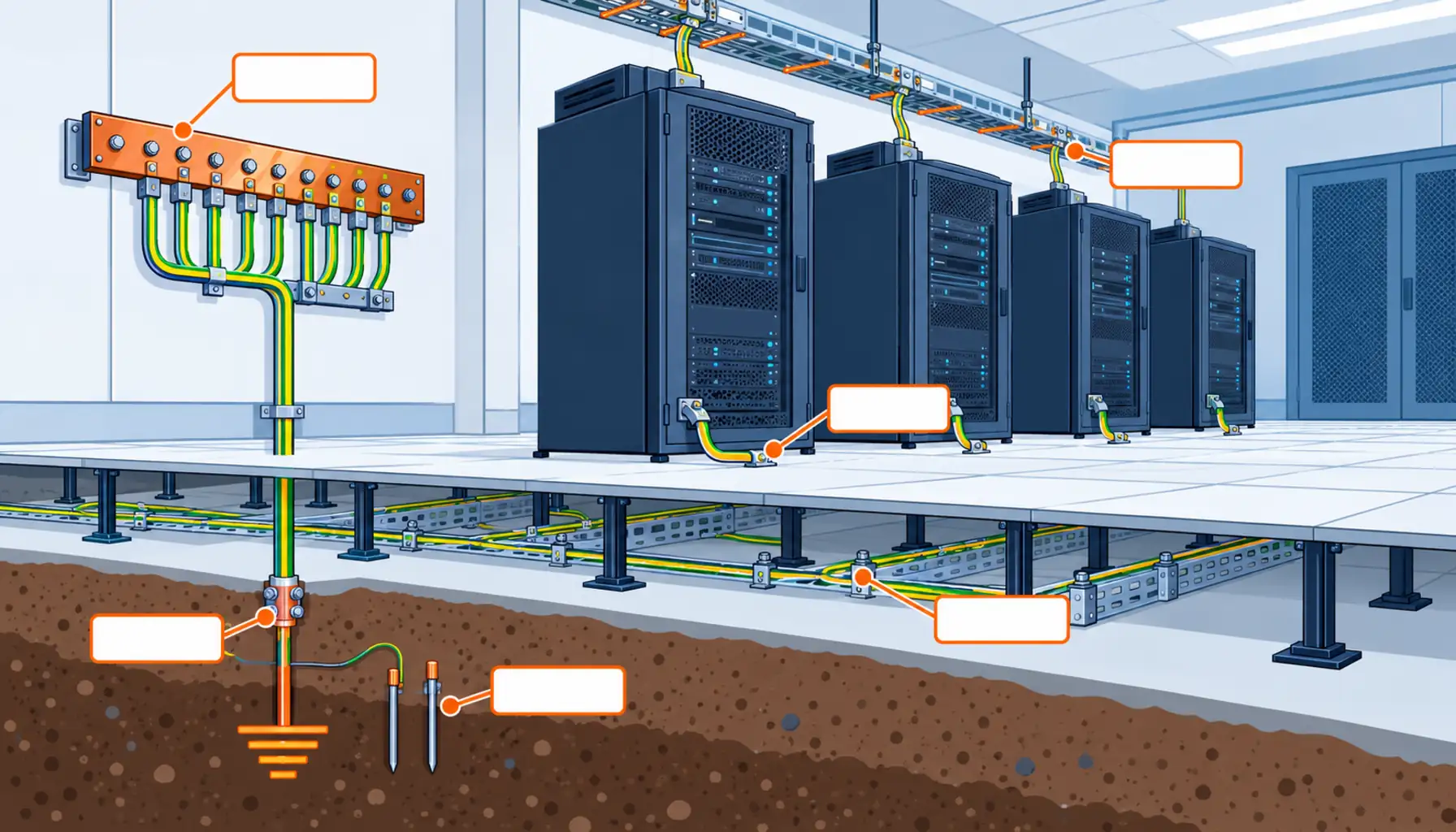
Quick Answer: Earthing is the only part of an electrical installation whose quality is determined by a hundred small connections, most of which are hidden behind closed ceilings and raised floors by the time anyone looks. Verification therefore has three parts and a buyer should specify all three: a visual inspection with photographs taken before the closures, continuity measurement of every protective and bonding conductor using an instrument that applies the required test current, and a whole-path measurement such as earth fault loop impedance that proves the chain works rather than proving each link exists.
Grounding gets treated as a compliance detail on most projects, and the cost of that treatment appears in the least convenient place. A missing bonding jumper between two cable tray sections behind a closed ceiling is not discovered by an inspection, because there is nothing to inspect. It is discovered during a fault, or during a condition survey years later, when the ceiling has to come down and the circuit has to be isolated. Every one of those situations costs more than the jumper would have.
Introduction
Two words are used interchangeably and describe different things. Grounding, or system earthing, is the connection of the system’s neutral or mid-point to earth and determines how the installation behaves during an earth fault. Bonding is the interconnection of all the metalwork that a person could touch and all the conductive parts that could carry fault current, so that no dangerous potential difference appears between them. A facility can have an excellent earth electrode and still be unsafe because a rack is not bonded to it.
That distinction matters commercially because the two are verified differently and bought from different scopes. The earth electrode is a civil and electrical interface work, usually included in the substation package. The bonding is a thousand small items installed by whoever is nearest, spread across the electrical, containment and fit-out packages, and nobody owns it end to end. The verification scope should cover both, and it should be written as an explicit list rather than as a single line item called earthing. The design side of this subject is covered separately in our note on data center grounding cable, and the continuity tests that overlap with it are in our note on insulation resistance and continuity testing.
The Three Measurements That Actually Verify the System
Each of the three answers a different question, and a verification scope that omits one of them leaves a real gap.
Continuity of protective and bonding conductors. A low-resistance measurement between the two ends of each conductor and between each bonded item and the main earthing terminal. The integrity of this measurement depends on the instrument applying enough current to overcome contact resistance at the probe tips and any oxide layers, which is why the standard for continuity test equipment requires a defined minimum test current rather than merely a resistance range. A measurement taken with too little current will happily report a low resistance through a connection that would fail under real fault conditions.
Earth electrode resistance. A measurement of the resistance between the earth electrode system and the general mass of earth. The method matters: the classical approach uses auxiliary probes placed at defined distances and measures the potential difference as they are moved, which is why it is called the fall of potential method. The clamp or stakeless method works only where there is a loop through the earthing system to measure, so it cannot be used on an isolated electrode and its results cannot be compared with fall of potential readings. Where the enquiry does not name the method, two contractors will return numbers measured in different ways, and neither will be able to justify its result against the design criterion.
Earth fault loop impedance. A measurement of the whole path from the point of fault back to the source through the protective conductor. This is the only one of the three that verifies the chain rather than its links, and it is the measurement that demonstrates the protective device will operate within the required time. A system can pass every individual continuity check and still fail on loop impedance, usually because the path is longer than the design assumed, or because a joint somewhere has a higher resistance than its measurement suggested.
The Decision Table: Verification Scope Compared
The table below compares verification scopes as a buyer would price them. The last two columns describe the commercial consequences, which for earthing are almost always about rework inside a finished building.
| Scope | What to Specify | Evidence You Receive | Cost and Programme Shape | Failure Mode If Chosen Wrong |
|---|---|---|---|---|
| Visual inspection only | The inspection list, and photographs of every connection before it is covered | Signed inspection sheets with images keyed to the drawing | Cheapest option, and it must happen before the closures, not after | Connections that look present and are not electrically continuous |
| Continuity measurement per conductor | Instrument with the required test current, the calculated maximum per run, and the record fields | Per-conductor readings with instrument and calibration references | Modest labour, high item count: hundreds of measurements on a large hall | A bonded-looking system with individual links that fail under fault current |
| Continuity plus electrode measurement | The method for electrode resistance, the electrode layout, and the seasonal conditions recorded | Electrode resistance with the method named, plus per-conductor continuity | Adds a site visit and probe installation; needs the soil accessible | Numbers from different methods compared as if they were equivalent |
| Whole-path loop impedance verification | The points at which loop impedance is measured, and the disconnection time each must satisfy | Per-point impedance readings checked against the protection settings | Most valuable measurement per hour spent; requires the installation energised | Individual checks passed and the path still unable to operate the protective device |
| Independent witness of all of the above | Which measurements are witnessed and at which milestone | Signed witness records plus the contractor's own records | Moderate cost; the witness has to be present before the ceilings close | Earthing verified after the only opportunity to correct it has passed |
The Cost of Bonding That Gets Buried
Almost every expensive earthing problem on a data center project has the same shape: the defect was created early, covered later, and discovered after the building was occupied.
The sequence is predictable. Bonding jumpers between tray sections are installed by the containment crew, who are working under programme pressure and whose quality check is that the jumper is present. The tray is then loaded with cable, the ceiling or the floor is closed, and the fire stopping is installed over the penetrations. By the time the earthing verification is performed, the only items still accessible are the ones that were always accessible, and the rest are verified by assumption. Our note on buying cable tray for high-density halls covers where the bonding continuity requirement belongs in that package.
Three measures make this manageable and none of them is expensive.
Move the verification earlier. The continuity measurement of each bonding connection should happen as the connection is made, recorded against a bonding schedule with a line per item. Verification at handover then becomes a check of the records plus a sample re-measurement, rather than a first attempt. The bonding schedule is the deliverable that makes this possible, and it should be prepared from the earthing drawing rather than assembled afterwards from memory.
Photograph before closing. A photograph of each bonding connection in place, keyed to the schedule, costs nothing and is the only evidence that will exist once the ceiling is closed. The same discipline applies to fire stopping, and the two records are usually produced by different people, which is why our note on firestop cable penetration systems makes the same argument for the penetration register.
Name an owner. Earthing spans the substation package, the containment package, the fit-out package and the equipment installation. Assigning the verification to a single party, even when the installation is spread across several, is what prevents the assumption that somebody else has checked it.
Instruments and Test Current: Why a Cheap Ohmmeter Is Not Enough
The measurement that looks simplest is the one most often compromised.
Continuity of protective conductors is a low-resistance measurement, and low-resistance measurements are sensitive to the test current applied. Standards for continuity test equipment require a defined minimum test current precisely because contact resistance at the probe tips and any surface film on the conductor can dominate the reading at very low currents. An instrument that applies a small current through a dirty terminal can read a resistance that passes a criterion while the actual connection would heat and fail under fault current.
Three requirements belong in the specification as a result.
Test current. The instrument must apply the minimum current the verification standard requires for protective conductor continuity, and the record should state which instrument was used. Confirming the current capability of the instrument offered is a two-line question in the enquiry and it removes a whole category of unverifiable evidence.
Calibration. Instruments used for verification need calibration in date and traceable, referenced on every record. This is the same discipline as the insulation resistance records, and it carries the same consequence if omitted, which is that the evidence cannot be relied on when a defect appears.
Four-terminal measurement where the values are small. At very low resistances, the resistance of the test leads themselves becomes significant, and a two-terminal measurement includes it. Instruments that compensate for lead resistance, or four-terminal methods, avoid reporting lead resistance as part of the installation.
None of these requirements adds cost to a competent contractor’s existing practice. They add cost only to a contractor who was planning to use whatever instrument was at hand, and that is exactly the case the specification needs to exclude. The wider evidence set these records feed into is covered in our note on TIA-942 certification testing.
What to Freeze Before the Earthing Works Are Covered
| Item | What to State | Evidence to Attach | Cost of Leaving It Open |
|---|---|---|---|
| Bonding schedule | A line per bonded item, derived from the earthing drawing, with the connection type and location | Schedule issued to the installing trades before the work starts | Nobody knows how many connections should exist, so nobody can tell whether one is missing |
| Inspection timing | That visual inspection and continuity measurement happen before the ceilings and floors close | Signed sheets dated before the closure, with photographs | Verification performed against a finished building, with sampling instead of checking |
| Continuity criteria | The calculated maximum resistance per conductor run, in writing | Calculation referenced in the test plan | Measurements accepted on impression, and no basis for rejecting a marginal one |
| Electrode measurement method | Which method is required, with the probe layout and distances for fall of potential | Record naming the method, with conditions and probe spacing | Clamp readings and probe readings compared as if equivalent, with neither justified |
| Loop impedance points | The points to be measured and the disconnection time each must satisfy | Per-point readings checked against the protection settings | Individual links verified and the protective device never proven to operate |
| Instrument specification | Minimum test current for continuity, calibration in date, and lead compensation | Instrument datasheet plus calibration certificates | Low-current readings through dirty terminals, reported as passes |
| Ownership of the scope | Which party verifies earthing end to end, across all the packages involved | Named responsibility in each contract | Each trade verifies its own work and the interfaces between them go unchecked |
| Re-verification trigger | That affected circuits are re-verified after any later works that disturb the path | Written procedure issued with the handover documentation | A bonding connection removed by a later trade and never restored |
When a Separate Clean Earth Is Not the Answer
Separate earthing systems for sensitive equipment are a recurring requirement on data center projects, and they are usually the wrong purchase.
The safety argument. Where two earthing systems exist and are not bonded together, a fault in one can raise its potential relative to the other, and anything that bridges the two, including a person and a signal cable, becomes part of the fault path. The reason the standards require a single bonded earthing system is not a preference for simplicity; it is that a single system cannot develop a dangerous potential difference within itself.
The noise argument. What sensitive equipment actually needs is a low-impedance equipotential reference, not an isolated one. Bonding equipment to a properly designed and verified equipotential system, and keeping signal and power routes separated, addresses the real problem. An isolated earth usually makes interference worse, because it creates a loop where none existed. The signal-side view of that is covered in our note on network data cables.
Where a separate system is genuinely required. There are specific applications, usually involving medical or specialist equipment, where a separated system is specified along with monitoring and a defined isolation arrangement. Those cases come with their own verification requirements and their own monitoring equipment, and they are not the same thing as an unbonded earth installed because someone asked for a clean one.
Where the placement of the electrode is the real issue. If the concern is the resistance of the electrode or the impedance of the path rather than noise, the answer is a better electrode arrangement or a shorter, larger protective conductor, and it is decided at design stage alongside the rest of the data center power distribution rather than by adding a second earthing system after the building is finished.
RFQ Checklist
- Bonding schedule derived from the earthing drawing, with a line per connection and a location reference
- Inspection and continuity verification scheduled before ceilings and floors close, not after
- Calculated maximum resistance per protective conductor run, provided in writing
- Earth electrode measurement method named, with probe layout and spacing for the fall of potential test
- Loop impedance measurement points listed, with the disconnection time each must satisfy
- Continuity instrument minimum test current stated, with calibration certificates supplied
- Compensation for test lead resistance required at low values
- Non-conductive surfaces identified in advance, with the bonding method for each one specified
- Photographic record of every connection before concealment, keyed to the bonding schedule
- A named party responsible for verifying earthing across all installation packages
- Re-verification requirement after later works that could disturb the path
- All records delivered in editable form, per item, as a contractual deliverable
Conclusion
Earthing verification is two purchases rather than one: an electrode and system earth that is measured properly, and a bonding installation that is checked before it disappears behind a ceiling. The three measurements that matter are continuity with an instrument applying the required test current, electrode resistance by a named method, and loop impedance at defined points to prove the path operates the protection. Freeze those, put a bonding schedule in the hands of the installing trades, and the earthing system stops being the item everyone assumed someone else had checked.
Kexingyu Cable Group (KXYE) supplies the cable and distribution equipment that earthing systems are built around, including the WDZ-YJY, WDZN-YJY, BTTZ, BBTRZ, NG-A (BTLY), KVV and YJV ranges, the multi-purpose distribution cable used on submain routes, and the GGD power distribution cabinet and KYN28 medium voltage switchgear at the origin of the fault path, all from one factory group with copper price linkage available on project-scale orders. Send your earthing drawing with the bonding items you intend to verify, and we will return the conductor and bonding data the schedule needs, item by item; the fastest route is a request for quotation.


