
Procuring Islanding and Grid Transfer Capability for Data Centers: Protection, Controls and Test Evidence
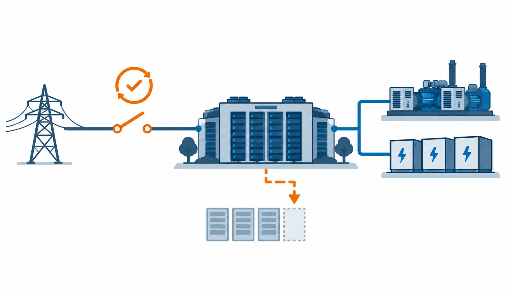
Quick Answer: Islanding capability is bought at one place: the point where the campus separates from the grid. What has to be specified there is the separation device, the anti islanding protection and its detection time, the synchronising equipment for reconnection, and the control scheme that balances the islanded load against available generation. None of it is visible in a generator order, and all of it decides whether the campus can actually run disconnected.
Introduction
A campus with on-site generation is often described as able to run independently. Whether it can is decided by a handful of devices at the incomer, most of which are not in the generation package and are not in the utility’s scope either, which is why they are the items most often left unpriced.
The generation options themselves are covered in our notes on generator and storage hybrid systems and on critical power backup requirements. This note deals with the boundary between the campus and the network, which is the same for every generation technology and is where the utility will look first. Our note on dual source incoming supplies covers the arrangement on the other side of the same boundary.
What Islanding Actually Requires
Running an island is four functions working together, and buying only one of them is the usual mistake.
Separation. A device at the point of connection that opens to disconnect the campus from the network, with a rating for the current it may have to interrupt and a defined operating time. Where the campus exports at any point, the device has to be rated for that direction of power flow as well.
Detection. Protection that identifies the loss of the grid and trips the connection within a time the utility accepts. This is not only a reliability function, it is a safety requirement, because a network that remains energised from a customer installation endangers utility staff working on it.
Regulation. Governor, automatic voltage regulator or inverter control with the droop settings that let the island carry its own load when the grid is no longer providing the reference. An island without a reference is only stable if something in it is controlling frequency and voltage.
Balance and load management. A scheme that sheds or restores load to keep generation and demand within the island’s capability. Generation step and load step rarely match, so the control scheme rather than the machine decides the island’s survival.
The Decision Table: Islanding and Transfer Arrangements Compared
The four arrangements below cover most campus designs. Each one changes what equipment is bought and what has to be tested.
| Arrangement | What You Are Buying | What to Specify | Evidence You Should Receive | Risk and Operating Shape |
|---|---|---|---|---|
| Mechanical transfer and standby | A changeover device between grid and generation, with an open transition and no parallel running | Switching time, rating, load step accepted, anti islanding protection and its detection time | Switching time test at load, protection test records, utility acceptance of the scheme | Simple and easy to witness; a break in supply, so the load has to ride through it |
| Static transfer with island control | A fast changeover device plus control that can hold an island while generation takes the load | Transfer time, island frequency and voltage windows, droop settings, load shedding steps | Island mode test at real load, transfer in both directions, control response records | Fast and suitable for sensitive load; needs a control system that is tested, not just configured |
| Generator island with load management | Synchronising, governor control and a load shedding scheme built around the generator step size | Generation step, block load acceptance, shedding priority order, block load rejection behaviour | Load acceptance and rejection tests, shedding sequence test, frequency excursion records | Common on large campuses; the island collapses if the shedding order does not match the real load priority |
| Inverter based island | Storage or fuel cell inverters with grid forming capability and a defined transition to island mode | Grid forming or following mode, transition method, ride through settings, certification level | Certification to the applicable standard, transition tests, frequency and voltage support records | Fast and precise; depends on certification and on firmware versions that have to match what is installed |
What to Specify at the Point of Connection
Six items turn an islanding intention into a purchasable scheme.
The separation point and its rating. Where the campus separates, the device that does it, its interrupting rating and its operating time. Where more than one connection point exists, the scheme has to be defined for each, including the case where only one is lost.
Anti islanding protection and detection time. The method, passive or active, and the time within which the connection must open. The utility sets an upper limit, and the specified figure should be the one that will be tested.
Synchronising and reconnection. The equipment that checks voltage, frequency, phase angle and rotation before the connection is closed, and the permitted reconnection method. Closing out of phase is the single most damaging event in this scheme. Our note on generator synchronisation systems covers the devices that perform this function.
The island operating envelope. The load range the island will run in, the frequency and voltage limits the control will hold, and the duration for which it is expected to persist. An island designed for twenty minutes and used for eight hours has a fuel and maintenance consequence nobody bought.
Load shedding and restoration. The priority order, the shedding step size against the generation step, and the conditions under which load is restored. Where the shedding scheme is left to commissioning, it will be configured to whatever the load happened to be on the test day.
Interfaces and annunciation. What the operations team sees, how the modes are indicated and how the scheme is blocked for maintenance. A scheme that cannot be seen in the control room is a scheme that will be operated incorrectly. Our note on automatic and static transfer covers the device selection that sits behind these choices.
What to Verify Before Handover
Islanding is proven by tests that are inconvenient to arrange and therefore frequently reduced. Four of them matter.
Transition to island at real load. The campus is separated from the grid with the load connected, and the island is confirmed to hold. Testing at light load proves very little, because the difficult cases are the load steps and the reactive power balance at high load.
Reconnection and resynchronisation. The campus reconnects, with the synchronising check verified and the power flow after closing measured. Both directions should be tested, and any export limitation confirmed at the connection point rather than assumed from settings.
Anti islanding protection operation. The protection is proven to operate within the specified time, with the test method agreed with the utility in advance. This is the test the utility will ask for in evidence, and its acceptance is what makes the scheme legal as well as functional.
Load shedding and restoration sequence. The shedding order is exercised and compared with the intended priority list, then the restoration is exercised in the reverse order without tripping the source. Our note on inverter grid code compliance covers the certification position where inverters form part of the scheme.
What to Freeze Before the Order
| Item | What to State | Evidence to Attach | Cost of Leaving It Open |
|---|---|---|---|
| Separation point | Where the campus separates, which device performs it and its rating for both directions of power flow | A single line diagram with the separation point marked for each connection | A scheme that isolates the wrong section, or a device that cannot interrupt the current it sees |
| Anti islanding requirement | The detection method and the maximum time to open, as accepted by the utility | The utility's requirement in writing, and the test method to prove it | A scheme that fails its utility acceptance and delays energisation |
| Synchronising equipment | The check function, its settings and the permitted reconnection method | A synchronising scheme drawing and the settings schedule | A closure out of phase and damage that no warranty covers quickly |
| Island operating envelope | Load range, frequency and voltage limits, and the expected duration | A dynamic study or documented operating assumptions | An island that cannot hold the load, or a fuel and maintenance cost nobody planned |
| Load shedding scheme | The priority order, the shed step size and the restoration conditions | A shedding matrix with the load list behind it | An island that collapses under a step the shedding scheme did not anticipate |
| Control and annunciation | Mode indication, blocking facility and the alarms the operators will see | A control interface schedule and an alarm list | A scheme routinely defeated or misoperated because nobody can see its state |
| Test programme | The tests, the load at which they are performed, and the witness points | A test schedule with pass criteria and measured values | An island accepted on the basis of a light load demonstration |
| Operating procedure | The sequence to separate, to run islanded and to reconnect, with the responsibilities named | A written procedure issued before handover | A functional scheme that the site cannot use confidently during an event |
When Islanding Is Not the Answer
Where the site has no intention of running disconnected. Islanding carries protection, testing and utility obligations. A campus that will always transfer to standby and then reconnect should buy the transfer scheme and not the island, and should say so in the specification rather than leaving the capability half built.
Where generation and load cannot be balanced. An island that cannot follow its load will collapse, and the collapse is a full outage. Where the generation step is far larger or far smaller than the load blocks, the scheme should include storage or a load management strategy that makes the balance achievable.
Where the protection cannot be tested. An anti islanding scheme that has never been proven to operate within its time is a scheme with an unquantified risk. Where the test cannot be arranged, the design assumption should be that the protection may not operate, and the consequence should be accepted knowingly.
Where the utility has not been consulted. The reconnection conditions, the export position and the protection requirements are set by the network operator, not by the campus. A scheme designed without that conversation is a scheme that will be modified at the utility’s insistence, usually late. Our note on redundant power feeds and cable covers the incoming arrangement that the island connects back into.
RFQ Checklist
- Separation point identified for every connection, with the device and its interrupting rating stated
- Anti islanding method and maximum detection time confirmed with the utility in writing
- Synchronising check function specified, with settings and the permitted closing method
- Island operating envelope stated, including load range and expected duration
- Load shedding priority matrix supplied with the load list behind it
- Frequency and voltage limits stated for island mode, with the control that holds them
- Generator and inverter control modes specified, including grid forming where used
- Switchgear rating checked against the fault level in island mode as well as grid mode
- Black start capability defined and tested where the island may have to be formed from cold
- Control room indication and blocking facility included in the scope
- Test programme issued with the load at which each test will be performed
- Operating procedure and responsibilities issued before handover, not after
Conclusion
Islanding is bought at the boundary, in a handful of devices and a control scheme, and it is proven by a test programme that most projects would rather shorten. The devices are not expensive relative to the generation they serve, and the test is not expensive relative to the outage it prevents. What makes the difference is deciding early whether the campus is intended to run disconnected, and then buying that intention rather than describing it in a design narrative.
Kexingyu Cable Group (KXYE) supplies the equipment at and either side of the separation point, including the medium voltage switchgear and the dual power ATS cabinet used where a changeover carries the transfer, the cable and terminations for the incomer and generator routes, and the protection and metering equipment that supports the control scheme, all from one factory group with copper price linkage on project-scale orders. Send the separation arrangement and the island load profile you intend to run, and we will return the ratings, the interlocking schedule and the test records that let the mode change be demonstrated before handover; the fastest route is a request for quotation.


