
How Liquid Cooling Changes Cable Selection in AI Facilities
Quick Answer: Liquid cooling does not change what cable is — it changes the numbers: more current, higher temperatures and tighter routing push conductor sizing and verification up a level. Liquid cooling arrived in AI facilities as a thermal technology and stayed as an electrical one. Once racks crossed the densities where air gave up, everything around the rack — including the cable that feeds it — inherited a new environment: hotter local ambients, coolant lines sharing the routing space, heavier feeders per position, and a mechanical world where pipes and cables compete for the same metres. This guide translates the cooling transition into cable selection terms for buyers and specifiers.
Introduction
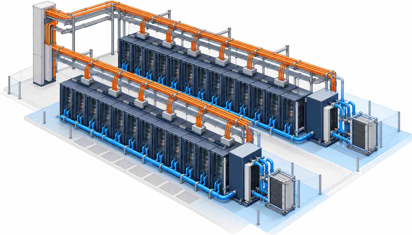
An air-cooled hall designed around 8 to 12 kW racks feeds each position modestly; an AI hall running 30 to 100 kW and beyond feeds each position like a small workshop. The cable consequence is arithmetic: busway ratings rise, tap-off capacities rise, and the fixed routes — from busway riser to row, from PDU to rack group — carry currents that push conductor cross-sections up one or two sizes. Parallel single-core sets become routine at rack-group level, and the tray space they demand collides with the coolant piping demanding the same space.
The routing collision is a design-phase problem, not a procurement one, but it has a procurement consequence: route lengths change, bends multiply, and pulling tensions rise. Feeder assemblies should be ordered against measured routes from the coordinated drawings — the discipline that proper cable size selection starts from — because a route drawn around manifolds is longer and tighter than the route an air-cooled design assumed. Factories that cut and terminate to measured lengths earn their keep twice in liquid-cooled halls.
More Current per Rack: The Feeder Consequence
An air-cooled hall designed around 8 to 12 kW racks feeds each position modestly; an AI hall running 30 to 100 kW and beyond feeds each position like a small workshop. The cable consequence is arithmetic: busway ratings rise, tap-off capacities rise, and the fixed routes — from busway riser to row, from PDU to rack group — carry currents that push conductor cross-sections up one or two sizes. Parallel single-core sets become routine at rack-group level, and the tray space they demand collides with the coolant piping demanding the same space.
The routing collision is a design-phase problem, not a procurement one, but it has a procurement consequence: route lengths change, bends multiply, and pulling tensions rise. Feeder assemblies should be ordered against measured routes from the coordinated drawings — the discipline that proper cable size selection starts from — because a route drawn around manifolds is longer and tighter than the route an air-cooled design assumed. Factories that cut and terminate to measured lengths earn their keep twice in liquid-cooled halls.
Hotter Local Ambients: Ampacity and the Derating Review
Liquid cooling removes heat from chips with great efficiency, but it relocates rather than vanishes it: heat exchangers, coolant distribution units and rear-door rejects all warm their corners of the hall. Local ambients above rack rows and near CDUs can sit well above the 30 degree reference that ampacity tables assume, and grouped feeders in shared trays compound the correction. The specifier’s job is unchanged in method but sharper in inputs: take real temperatures from the cooling design at the actual routing zones, apply ambient and grouping factors per route, and record them — the practice that separates engineered halls from copied schedules, and one that matters more as data center power demand growth concentrates ever denser compute into the same footprints.
Insulation handles the temperatures comfortably — cross-linked polyethylene, whose properties we explain in the guide to XLPE cable, rates at 90 degrees continuous with margin. What tighter ambients actually consume is margin: a route that was comfortably sized at reference ambient becomes merely adequate after derating, and merely adequate has no room for the next GPU refresh. Sizing the fixed infrastructure for the end-state density, not the first deployment, is the single cheapest future-proofing a liquid-cooled hall can buy.
Wet Environments: Sheath and Material Compatibility
Direct-to-chip systems move coolant in sealed loops, but sealed loops have joints, and joints have failure statistics. Cable that shares routing space with coolant lines — under raised floors, above rack rows, in CDU plant zones — should be selected as if exposure will happen, because statistically it will. The sheath questions are specific: resistance to the coolant chemistry in use, typically glycol-water mixtures for direct-to-chip systems and dielectric fluids for immersion; behavior at the temperatures a leak-adjacent zone can reach; and drip-loop geometry that keeps a leak from wicking along the cable toward connectors.
Immersion cooling is the intensive case: tanks of dielectric fluid with cable and connectors submerged or semi-submerged, where the fluid and every jacket material in the tank must be qualified as a pair. Material compatibility is tested, not assumed — sheath compounds swell or embrittle differently in different fluids — and the verification belongs in the specification as a named compatibility requirement with evidence, in the same way fire performance is evidenced rather than asserted. For most direct-to-chip halls the exposure is occasional rather than continuous, and a robust LSZH sheath with sensible drip geometry covers the realistic case; the zone near the CDU and the manifolds deserves the deliberate review.
Monitoring, Grounding and the Small Cable That Grew
Liquid cooling multiplies instrumentation: leak detection ropes, coolant temperature and pressure sensors, CDU control wiring, rack-level telemetry. The multi-core control and shielded communication scope grows accordingly, and its segregation from the fatter power routes must be re-planned rather than inherited — the rules that govern control and shielding are laid out in the control and instrumentation cable guide. Grounding follows the racks too: denser metallic plant, more bonded surfaces and the same equipotential logic, executed in smaller conductors at more points.
None of this is exotic; it is the standard cable families re-quantified for a denser, warmer, wetter hall. The failure mode this article exists to prevent is the copied schedule — a bill of quantities lifted from an air-cooled project and pasted into a liquid-cooled one, with undersized routes, unreviewed ambients and no compatibility clause for the zones that need one.
| Selection Aspect | Air-Cooled Baseline | Liquid-Cooled Adjustment |
|---|---|---|
| Rack feeder ampacity | 8-12 kW racks; modest tap-off and row feeder sizes | 30-100 kW+ racks; larger cross-sections, parallel sets routine, busway ratings up |
| Ambient assumption | Hall ambient near 25-30 C; standard derating inputs | Local ambients near CDUs, manifolds and rear doors higher; per-route review mandatory |
| Tray routing | Cable owns the tray and floor void | Shared territory with coolant piping; longer, tighter routes; pulling tension reviewed |
| Sheath chemistry | LSZH selected for smoke and halogen behavior | LSZH retained plus coolant compatibility reviewed; CDU and manifold zones deliberate choice |
| Immersion tanks | Not applicable | Jacket and fluid qualified as a pair, with test evidence named in the specification |
| Control and monitoring scope | BMS and telemetry at room level | Leak detection, coolant sensors and CDU control multiply the multi-core scope |
| Future-proofing | Sized to first deployment | Fixed routes sized to end-state density; GPU refresh absorbed without re-pull |
Zone by Zone: Where the Risks Actually Sit
Liquid-cooled halls are not uniformly wet or uniformly hot; they are zoned. The rack aisle sees the highest power density but usually dry routing above the manifolds. The CDU plant zone sees the wettest, warmest conditions and the heaviest plant cabling. The underfloor and overhead voids see shared routing. Distributing the requirements by zone turns a vague “liquid cooling specification” into a checkable cable schedule — the allocation below is the working pattern.
| Zone | Dominant Risk | Cable Requirement to Specify |
|---|---|---|
| Rack aisles and manifolds | High current density; occasional drip exposure | Upsized feeders sized to end-state density; robust LSZH sheaths; drip loops at entries |
| CDU and heat exchanger plant zone | Warmest ambient; most likely wet zone | Per-route derating from real ambient; coolant-compatible sheaths; segregated control cabling |
| Underfloor and overhead voids | Shared routing with coolant lines | Route survey from coordinated drawings; separation distances; mechanical protection at crossings |
| Immersion tanks, where used | Continuous fluid contact | Jacket-fluid compatibility tested as a pair; connectors qualified for submersion |
| Battery and UPS rooms behind liquid-cooled loads | Higher and less predictable DC and AC loading | Grouping derating rechecked; Class 5 flexible routes as for conventional power rooms |
When Liquid Cooling Should Not Change the Cable Decision
The first discipline is not over-reacting on compound selection. A direct-to-chip hall with sealed loops and sensible drip geometry does not need exotic fluid-proof jackets across the whole hall; it needs standard robust sheaths plus a deliberate, evidenced choice in the zones that can actually get wet. Specifying immersion-grade compatibility everywhere prices the hall like a tank farm and buys nothing where exposure cannot occur.
The second discipline is not re-derating blindly. Local hot zones deserve per-route correction, but the hall’s general ambient may barely move — the cooling design removes heat efficiently, and blanket derating across every route wastes copper on paper fears. The third is proportionality on monitoring: leak detection and sensor scopes should come from the cooling design’s failure analysis, not from padding the control schedule. Liquid cooling changes specific inputs at specific zones; the engineering task is to find those zones, not to multiply every number by a sense of drama.
RFQ Checklist: Cable for a Liquid-Cooled AI Hall
- Coordinated drawings with coolant routes and cable routes resolved, and measured route lengths
- Rack density end-state per row, with the feeder topology it implies
- Local ambient temperatures per routing zone from the cooling design, for derating inputs
- Coolant chemistry and the zones of possible exposure, for sheath compatibility review
- Immersion fluid type and tank cable scope, where applicable
- Conductor classes and parallel-set topology for high-current routes
- LSZH requirements per zone as for any modern hall
- Expanded control and monitoring schedule: leak detection, CDU and sensor cabling
- Assembly-level delivery: cut-to-length, factory-terminated, documented per circuit
- Commercial basis: copper price linkage across the program, validity by lot
An offer that restates these inputs per route is an engineered offer. One that prices from a legacy schedule is selling last year’s hall.
Conclusion
Liquid cooling rewrites the cable specification through four doors: more current per rack, hotter local ambients, wetter zones and a fatter monitoring scope. None of the cable families changes; the inputs, the zones and the evidence behind them do. The halls that commission smoothly are the ones whose schedules were redrawn from the cooling design rather than copied from an air-cooled past.
When you are specifying the cable scope for an AI facility, work with a manufacturer that can size, cut and document per route — and that will put sheath compatibility in writing where the zone demands it. Kexingyu Cable Group (KXYE) supplies the power, control and LSZH families from one factory group, factory-terminated to measured routes and quoted against a copper price linkage. Send the coordinated drawings and the cooling zone map, and we will return a route-by-route offer.


